Splines problem

If you are having problems with QCAD, post here. Please report bugs through our Bug Tracker instead.

Always attach your original DXF or DWG file and mentions your QCAD version and the platform you are on.

Moderator: andrew

Forum rules

Always indicate your operating system and QCAD version.

Attach drawing files and screenshots.

Post one question per topic.

Post Reply
Marek C
Newbie Member
Posts: 4
Joined: Mon Feb 28, 2022 2:19 pm

Splines problem

Post by Marek C » Thu Mar 21, 2024 12:27 am

Hello,
I am using Windows 10 and QCAD/CAM 3.29.4.0 (3.29.4) Build Date: Feb 7 2024, Revision: 36a6423, Qt Version: 5.13.2.

Image
I would like to cut a simple shape like this image on my router (Genmitsu 3020). It is a rectangle with rounded corners, and there is a cutout on the right side, which I obtained using splines. As this is quite a soft and thin material (similar to ABS) I think one pass is sufficient. Unfortunately the QCAD-generated gcode gives such strange results as in the image.
Image.

Other gcode visualisation programs (including QCAD) give the same image.

I have noticed the following:
- In the generated gcode, the G90 (or G91) command does not appear.
- F0 (feed rate zero ?) appears several times.
- I have tried various CAM Configuration and Tools Profile settings - with no result.
- I select G-Code (G41/G42) [mm] as the gcode type.
- Interestingly, when I made a similar simpler drawing for the test (a rectangle with a spline curve instead of one side), everything works flawlessly.

Since I have run out of ideas - I am counting on the help of forum members.
Thank you in advance,

Marek.

CVH
Premier Member
Posts: 3480
Joined: Wed Sep 27, 2017 4:17 pm

Re: Splines problem

Post by CVH » Thu Mar 21, 2024 5:32 am

Marek,
Topic is posted under the QCAD Pro forum ...
Rather a topic for the QCAD/CAM forum: https://www.qcad.org/rsforum/viewforum.php?f=74

For reproducing this we need the DXF file, the source before CAM or the DXF saved after adding profiles with QCAD/CAM.
It is probably not spline related ... :|

G90/91 is included in several postprocessors.
But not in GCodeMM.js based on GCodeBase.js.
GCodeMM.js aka G-Code (G41/G42) [mm] is a generic postprocessor suited for the most basic G-Code interpreters.
You might want to select a more specific postprocessor depending your setup.
Or add a new custom postprocessor based on GCodeMM.js or the best suited.
Don't forget to alter the displayName & description if you define a custom one. :wink:
(Never alter standard postprocessors shipped with QCAD/CAM as these are replaced each new update)

F0 would mean that you did not specify the Feedrate for a tool or for the toolpath.

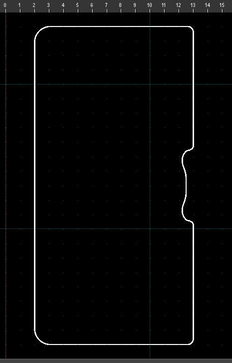
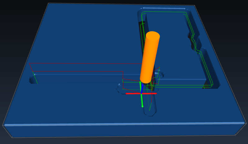
The crossing ends (lower middle) are presumed to be a Lead In/Out.
Mostly mandatory with G41/G42.
Use GCodeOffsetIN.js or GCodeOffsetMM.js as base to let QCAD/CAM calculate an offset path without G41/G42.
Or simply include this.outputOffsetPath = true in your custom postprocessor.

The extension to the left is probably just a far traverse to a plunge and back up where there is a dot or Null-Length entity.

You probably have not configured 'Save Z' very well as it cuts shallow while traversing (lower red trajectory).
Or the tool length that the simulator uses is probably a default ... :wink:
QCAD/CAM does not account for tool length or any compensation of that.
The main idea is that Z = zero correlates with the top of your material.
'Save Z' should be positive, above the substrate, 'Cut Depth' is that too in QCAD/CAM settings but the G-Code Z would be negative.
To account for tool length you also need to zero your setup in Z on the top of your material, usually best after zeroing it in X-Y.
How simulators handle this work zero depends ...
Marek C wrote:
Thu Mar 21, 2024 12:27 am
As this is quite a soft and thin material (similar to ABS) I think one pass is sufficient.
Probably yes but have you considered that the shape will be floating free near the end of the cut?
:!: When milled out as such your part can be pushed away or even grabbed by the cutter :!:
This is more of an issue when milling than with laser cutting but still ...
Or use a vacuum table, a sticky work-pad, double sided tape, ...
Or add retaining TABs see CAM menu .. Add Tab (KT)

Regards,
CVH

Marek C
Newbie Member
Posts: 4
Joined: Mon Feb 28, 2022 2:19 pm

Re: Splines problem

Post by Marek C » Thu Mar 21, 2024 11:18 pm

First of all - thanks for your quick and comprehensive reply. I probably made a lot of mistakes. But first of all - I don't have much experience at the moment, and besides I use rather amateur equipment which is not always well documented. For example, I have not been able to get a list of Gcodes accepted by my router. Hence, it was only after a few failures that I discovered that G04 requires time in seconds (not milliseconds as usual) etc.

Indeed I should have included dxf files and perhaps others. I am now completing this (in attachment). If the number of errors raises your blood pressure - sorry. ;-)

P. S. 1. Thanks for the warning about the lack of tags. Of course I always add them at the end. I also always look at the gcode on the simulator first and then try it on some soft material (in my case it's a flower sponge). But this time when I saw the chaos on the simulator - I haven't even tried to run it yet. :-) First to understand - then to act. I think that's a good rule of thumb...
P. S. 2. I completely don't understand where the values S8000 and F120, which I didn't enter anywhere, came from in the code, and also why F0 is there when I specified a feed rate of 200.
Attachments
st-10.nc
(36.36 KiB) Downloaded 9 times
st-10.dxf
(828.27 KiB) Downloaded 8 times
CAM-configuration.jpg
CAM-configuration.jpg (31.54 KiB) Viewed 264 times
CAM Profile Toolpath.jpg
CAM Profile Toolpath.jpg (32.79 KiB) Viewed 264 times
Add CAM Tool.jpg
Add CAM Tool.jpg (12.14 KiB) Viewed 264 times

CVH
Premier Member
Posts: 3480
Joined: Wed Sep 27, 2017 4:17 pm

Re: Splines problem

Post by CVH » Fri Mar 22, 2024 7:57 am

Hi,
A quick search about "Genmitsu 3020" revealed these Grbl V1.1 supported G-Code:
https://www.sainsmart.com/blogs/news/gr ... rtedGCodes

And indeed G4 in seconds ... :roll:
Also from this list:
  • G40 Cutter Compensation off. Grbl does not support cutter compensation.
You are probably better of with a specific Grbl postprocessor, one that creates an offset path for compensation.
What version is your setup running?

Here I need to add that some (free) simulators don't support G41/42 either.

There are 11 Toolpaths in your dxf, 1 without a name.
11 trials probably, type the shortcut GA for a list of Toolpaths.
10 (named) will end up in your G-code export ... => 10 entries like N... G2 X10.8976 Y13.7694 I-12.1122 J0.0116
You only need one Toolpath, with 1 pass, I think you should start over from scratch.

S8000 ... I can detect CamSpindleSpeed = 8000 in CAMTOOL$$GCodeMM$$2
Meaning that at least one CAM Configuration was set with SPEED 8000.
F120 ... At least the same configuration has recorded that you opted for FEED 120.

First line of your nc file: N10 G0 Z0
This is dangerous stuff, especially when the setup is not zeroed properly.
Origin: CAM Configuration .. Z Levels .. Safety level (for tool changes and end)
And thus also for startup. :wink:
Choose a main safety level wisely, as high as possible to avoid for example clamps and so.
(My engraving setup does that in machine coordinates to be utterly certain, Zhome = top = Zwork 62, Safety level = G53 G0 Z60)
Going down from there is usually handled with a G0 = rapid. (My diagonal G0 feed can be over 3000 :wink: )
Choose a Toolpath 'Save Z' so that local rapid moves are freely above the substrate but not too high there every plunge to cut starts there.

In my book a plunge rate of 0.4 would mean that the cutters plunges with 0.4mm per minute.
(FEED is in units/minute, presumed in millimeter, SPEED are rotations/minute)
Plunging down from 'Save' Z+5 to Z-1 would for example take about 15 minutes ... :roll:

I am missing the G20/21, rather odd that GCodeMM.js does not define a G-Code header with at least G21.
GrblMM.js aka GRBL (offset) [mm] does but that includes a link to https://carbide3d.com/shapeoko/.

Over to you. :wink:
Regards,
CVH

Post Reply

Return to “QCAD Troubleshooting and Problems”