File Tools
Toolbar / Icon:
![]()
Commands: filemenu
Description
The file menu contains all tools to open, save, import, export and print files.
New
Toolbar / Icon:
![]()
![]()
Menu: File > New
Shortcuts: Ctrl+N (Mac: ⌘N) | Ctrl+T (Mac: ⌘T)
Commands: new
Description
Create new, empty drawings using this command. New drawings are completely
empty (no entities, only one default layer, no blocks). As a frequent user of
QCAD, you might instead want to create drawing templates with the layers and
blocks you use the most and probably a drawing border. Once you have such a
template you can load that instead of starting a new drawing from scratch.
Please refer also to the command
New
from Template
to learn how to use drawing templates.
New from Template...
Toolbar / Icon:
![]()
![]()
Add-on:
![]() QCAD Professional
QCAD Professional
Menu: File > New from Template...
Shortcut: Ctrl+Shift+N (Mac: ⇧⌘N)
Commands: newfromtemplate
Description
This tool opens a drawing template as a starting point for a new drawing. Any regular drawing can be used as drawing template if it is stored in the library/templates directory or another template directory configured in the application preferences dialog.
Open…
Toolbar / Icon:
![]()
Menu: File > Open…
Shortcut: Ctrl+O (Mac: ⌘O)
Commands: open
Description
Use this command to open a drawing file. The file is loaded and shown in a new window within the QCAD application window. You can switch between different loaded drawings using the menu "Windows" or the tabs at the top of the drawing area.
QCAD Professional
PDF Files
If you open a PDF file, QCAD show a dialog. In this dialog, you can specify the page to import, if you want to import images and if clipping should be applied. Imported images are stored in a new folder called "pdf_images" located where the PDF file is located. Without clipping, all vector data is imported from the PDF file. This might include data outside the paper.
Editing CXF Fonts
QCAD comes with a collection of line fonts in its own CXF format.
Line fonts are sometimes used in CAD instead of TrueType fonts.
Line fonts are also often used for engraving or other further processing.
QCAD can load and edit fonts in CXF format. To load an existing font, simply
use the menu File > Open and choose the format filter "CXF Font Files
(*.cxf)". Then choose the font file you want to open. The fonts that come with
QCAD are stored in directory "fonts" of your QCAD installation.
The font glyphs (representation of the various letters and symbols) are loaded
into blocks. Make sure the block list is visible (View > Block List), so you
can navigate through the font glyphs.
Each block has a name in the format "[Hexadecimal Unicode] [Symbol]",
for example "0x0041 A" for a capital "A" with Unicode 65 (41 in hexadecimal).
By convention, a capital "A" should be constructed with a height of 9 drawing
units. When the font is used for a text, it is scaled by QCAD according to the
text height chosen.
Glyphs should have their reference point 0,0 at the lower left corner of the
base line. In the CXF format, glyphs can contain lines, arcs and polylines.
Splines may be used, but are converted into polylines during export.
Import…
Toolbar / Icon:
![]()
![]()
Menu: File > Import…
Shortcut: Ctrl+Shift+I (Mac: ⇧⌘I)
Commands: import
Description
The import command inserts a drawing from a file on disk into the current
drawing.
All layers that are used by the imported drawing are added to the
layer list of the current drawing. Existing layers with the same name can be
overwritten if desired ("overwrite layers" option in the options tool bar).
Block references of the imported drawing will be inserted together with
the block definitions they refer to. Blocks in the current drawing can be
overwritten if desired ("overwrite blocks" option in the options tool bar).
The options tool bar also offers some tools to scale, rotate or flip the
imported drawing while positioning it.
Usage
Set the target point for the imported drawing with the mouse or enter a coordinate in the command line. The target point corresponds to the absolute zero point of the imported drawing.
Revert
Toolbar / Icon:
![]()
![]()
Add-on:
![]() QCAD Professional
QCAD Professional
Menu: File > Revert
Shortcut: Ctrl+R (Mac: ⌘R)
Commands: revert
Description
Reloads the current drawing from disk. All unsaved changes are lost. Note that this operation cannot be undone. This function can for example be used to refresh the view if QCAD is used as file viewer for files which are modified by another application or process.
Show in Explorer / Finder / File Manager
Toolbar / Icon:
![]()
Add-on:
![]() QCAD Professional
QCAD Professional
Menu: File > Show in Explorer / Finder / File Manager
Shortcut: F, I
Commands: showfile
Description
This tool can be used to open the folder that contains the current drawing in a file manager window. This can be Explorer under Windows, Finder under macOS or a file manager such as Nautilus under Linux. Explorer and Finder will also highlight the drawing file in the folder.
Save
Toolbar / Icon:
![]()
![]()
Menu: File > Save
Shortcut: Ctrl+S (Mac: ⌘S)
Commands: save
Description
This command saves the current drawing to the same file it was loaded from. If you want to save a newly created drawing or save the current drawing to a new file, use the menu File - Save As instead. You will then be asked for a file name before the drawing is saved.
Save As...
Toolbar / Icon:
![]()
![]()
Menu: File > Save As...
Shortcut: Ctrl+Shift+S (Mac: ⇧⌘S)
Commands: saveas
Description
Saves the current drawing as a new file. The dialog that is shown also allows you to choose the format and format version that you want to use to save the file.
Close
Toolbar / Icon:
![]()
![]()
Menu: File > Close
Shortcut: Ctrl+W (Mac: ⌘W)
Commands: close
Description
This command closes the current drawing. If the current drawing contains unsaved changes, you will be given the option to save the drawing before closing it or to discard those changes.
Bitmap Export...
Toolbar / Icon:
![]()
![]()
Menu: File > Bitmap Export...
Shortcut: X, B
Commands: bitmapexport
Description
This tool exports the current drawing as a bitmap file.
Usage
A dialog for selecting the output file is presented. After the file name has
been specified, a second dialog asks you for the bitmap size and the preferred
background color.
Note that exporting to bitmaps with a very large size can take a long
time, depending on your hardware. The maximum size for bitmaps is width x
height ≤ 2.147.483.647.
Quick SVG Export…
Toolbar / Icon:
![]()
![]()
Add-on:
![]() QCAD Professional
QCAD Professional
Menu: File > Quick SVG Export…
Shortcut: X, S
Commands: svgexport
Description
Exports the current drawing to an SVG file. While the SVG format is not
ideal for storing CAD data, it is very popular for storing various types of
vector graphics mainly for presentation and sometimes for further processing.
This tool uses the parameters that can be configured in the application
preferences under Load/Save - Quick SVG Export.
Advanced SVG Export...
Toolbar / Icon:
![]()
![]()
Add-on:
![]() QCAD Professional
QCAD Professional
Menu: File > Advanced SVG Export...
Commands: svgexportas
Description
Exports the current drawing in the SVG format. An advanced export dialog is
shown that can be used to configure various options for the export.
Most notably, the option "Preserve Geometry" can be used to export the
drawing for further processing. The visual appearance of the output might not
exactly match that of the CAD drawing in this case, but as much of the geometry
as possible is carried across to the SVG file.
SVG Import...
Toolbar / Icon:
![]()
![]()
Menu: File > SVG Import...
Commands: svgimport
Description
This tool imports an SVG file into the current drawing. Note that only a very limited set of SVG tags and arguments is supported. The idea is to import as much of the raw geometry in the SVG file as possible.
PDF Export…
Toolbar / Icon:
![]()
![]()
Menu: File > PDF Export…
Shortcut: X, D
Commands: pdf
Description
This tool exports the current drawing to a PDF file. Exporting to PDF is
very similar to printing a drawing. You will most likely have to adjust
your drawing scale and drawing position as well as page settings before
exporting a drawing to PDF.
For this reason, QCAD automatically switches to the print preview when
this tool is used. If the print preview does not match your expectations,
cancel the export, adjust the page settings and start the PDF export again.
Print Preview
Toolbar / Icon:
![]()
![]()
Menu: File > Print Preview
Shortcut: Ctrl+Shift+P (Mac: ⇧⌘P)
Commands: printpreview
Description
The print preview shows how your drawing will look like in the printout. Use
the combo box in the options tool bar to adjust the scale factor of your
drawing. This option does not actually scale or otherwise modify your drawing
entities, it only sets up the scale factor that is applied for fitting your
drawing on paper.
The buttons right of the scale combo box can be used to automatically fit
your drawing on the chosen paper or to automatically add pages, so your entire
drawing can be printed on multiple pages.
After choosing the "Move Paper Position" tool, you can move the paper
around freely by dragging it with the left mouse button. Click the right mouse
button or hit the escape key to terminate the tool.
The options tool bar offers some other tools to quickly change some
common drawing preferences that are also accessible in the drawing preferences
dialog.
Print…
Toolbar / Icon:
![]()
![]()
Menu: File > Print…
Shortcut: Ctrl+P (Mac: ⌘P)
Commands: print
Description
Use this command to print a drawing. Make sure to always switch to the print
preview before printing to check if the drawing scale and position is set up as
desired.
A setup dialog is shown before anything is printed. Use this dialog to
choose the printer and adjust printer specific settings.
Print Current View…
Toolbar / Icon:
![]()
![]()
Menu: File > Print Current View…
Shortcut: Ctrl+Alt+P (Mac: ⌘Alt+P)
Commands: printview
Description
Use this command to print the drawing portion that is currently shown in the graphics view.
Print Window…
Toolbar / Icon:
![]()
![]()
Add-on:
![]() QCAD Professional
QCAD Professional
Menu: File > Print Window…
Shortcut: Ctrl+Alt+Shift+P (Mac: ⌘Alt+⇧P)
Commands: printwindow
Description
This tool prints a rectangular window of the drawing. The print preview is setup in such a way that the chosen rectangular area fits exactly on the printable area of the paper.
Edit Tools
Toolbar / Icon:
![]()
Commands: editmenu
Description
The edit menu contains tools for basic editing such as copy / paste and deleting.
Application Preferences…
Toolbar / Icon:
![]()
![]()
Menu: Edit > Application Preferences…
Shortcut: Ctrl+, (Mac: ⌘,)
Commands: preferences
Description
In the application preferences dialog, you can adjust the look and behavior
of QCAD and its tools and graphics views.
QCAD also stores some of these settings inside the drawings. Those
settings can be changed in the application preferences as default settings for
new drawings. In other words, they don't affect existing drawings but only
drawings that are created after the preferences have been changed.
Undo [-]
Toolbar / Icon:
![]()
![]()
Menu: Edit > Undo [-]
Shortcuts: Ctrl+Z (Mac: ⌘Z) | O, O
Commands: undo | oops
Description
This tool takes back the last change of the drawing. QCAD can take back more than one command. For example if you have just created a line and a circle and you want to undo both, use the undo command twice.
Redo [-]
Toolbar / Icon:
![]()
![]()
Menu: Edit > Redo [-]
Shortcuts: Ctrl+Shift+Z (Mac: ⇧⌘Z) | U, U
Commands: redo | uu
Description
Redo reverts the effects of the previous Undo Action.
Delete
Toolbar / Icon:
![]()
![]()
Menu: Edit > Delete
Shortcuts: Del | Backspace | E, R
Commands: delete | er
Description
This tool deletes the entities that are currently selected.
Cut
Toolbar / Icon:
![]()
![]()
Menu: Edit > Cut
Shortcut: Ctrl+X (Mac: ⌘X)
Commands: cut
Description
The Cut tool works like the Copy tool with the only difference that the selected entities are removed from the current drawing after being copied to the clipboard.
Cut with Reference
Toolbar / Icon:
![]()
![]()
Menu: Edit > Cut with Reference
Shortcuts: Ctrl+Shift+X (Mac: ⇧⌘X) | R, T
Commands: cutwithreference | rt
Description
The Cut with Reference tool works like the Copy with Reference tool with the only difference that the selected entities are removed from the current drawing after being copied to the clipboard.
Copy
Toolbar / Icon:
![]()
![]()
Menu: Edit > Copy
Shortcuts: Ctrl+C (Mac: ⌘C) | C, P
Commands: copy | cp
Description
QCAD offers a set of tools to copy entities from one drawing to another, similar like other applications.
Usage
- Use the selection tools to prepare a selection of entities you want to copy to the clipboard.
- Choose the copy tool.
The standard copy tool of QCAD acts like the copy tool of other applications. It does not allow you to choose a reference point for your selection but instead computes the reference point automatically at the center of the selection. This is not always desirable as you most likely want to place the pasted entities at a precisely defined position. For this, QCAD offers and alternative, more CAD specific copy tool: Copy with Reference.
The selection is now on the QCAD internal clipboard and can be pasted into the same or a different drawing that is opened with the same running instance of QCAD. Note that if you quit the QCAD application, the contents of the clipboard is lost. The QCAD clipboard can only be accessed by QCAD itself. You cannot exchange drawing entities with other applications through copy and paste. Please use the export and import functionality of QCAD for this.
Copy with Reference
Toolbar / Icon:
![]()
![]()
Menu: Edit > Copy with Reference
Shortcuts: Ctrl+Shift+C (Mac: ⇧⌘C) | R, C
Commands: copywithreference | rc
Description
Copies the current selection to the QCAD clipboard. This tool lets you specify a reference point that is used to position the selection when pasting it into a drawing.
Usage
- Use the selection tools to prepare a selection of entities you want to copy to the clipboard.
- Start the Copy with Reference tool.
- Specify the reference point that you want to use when pasting the selection.
Paste
Toolbar / Icon:
![]()
![]()
Menu: Edit > Paste
Shortcuts: Ctrl+V (Mac: ⌘V) | P, S
Commands: paste | ps
Description
The paste command inserts the entities that were previously copied to the
clipboard. Paste is especially useful to transfer entities from one drawing to
another.
All layers that are used by the clipboard contents are pasted into the
layer list of the current drawing. Existing layers with the same name can be
overwritten if desired ("overwrite layers" option in the options tool bar).
Block references that are on the clipboard will be pasted together with
the block definitions they refer to. Blocks in the current drawing can be
overwritten if desired ("overwrite blocks" option in the options tool bar).
The options tool bar also offers some tools to scale, rotate or flip the
clipboard contents while pasting.
Usage
Set the target point for the pasted entities with the mouse or enter a coordinate in the command line. The target point corresponds to the reference point that was chosen when copying or cutting the entities if Copy / Cut with Reference was used. If Cut or Copy without reference point was used, the center of the selection is used as reference point.
Paste along Entity
Toolbar / Icon:
![]()
![]()
Add-on:
![]() QCAD Professional
QCAD Professional
Menu: Edit > Paste along Entity
Shortcuts: Ctrl+Shift+V (Mac: ⇧⌘V) | P, E
Commands: pastealongentity
Description
This tool pastes the clipboard contents along an existing line, arc, polyline or spline entity. The clipboard is pasted multiple times in such a way that the reference point of the clipboard contents is placed on the entity.
The clipboard can be inserted multiple times with a given distance between items or a given number of times, equally spread along the entity.
The "Align" option can be used to rotate the clipboard to align its angle with the angle along the entity.
The "Include end points" option causes the first and last items to be placed on the start and end point of the entity.
In addition, the clipboard can be scaled or rotated while pasting.
Duplicate
Toolbar / Icon:
![]()
![]()
Menu: Edit > Duplicate
Shortcut: D, P
Commands: duplicate | dp
Description
This tool duplicates the selected entities and selects the created copy.
Usage
- Use the selection tools to prepare a selection of entities you want to duplicate.
- Choose the duplication tool.
Quick Modify Tools
Toolbar / Icon:
![]()
Shortcut: W, Q
Commands: quickmodifymenu
Move Left
Toolbar / Icon:
![]()
Add-on:
![]() QCAD Professional
QCAD Professional
Menu: Edit > Quick Modify > Move Left
Shortcut: ←
Description
This function can be used to quickly move the current selection by a
previously configured distance.
The distance can be configured under Edit > Application Preferences
> Edit > Move.
Move Right
Toolbar / Icon:
![]()
Add-on:
![]() QCAD Professional
QCAD Professional
Menu: Edit > Quick Modify > Move Right
Shortcut: →
Description
This function can be used to quickly move the current selection by a
previously configured distance.
The distance can be configured under Edit > Application Preferences
> Edit > Move.
Move Up
Toolbar / Icon:
![]()
Add-on:
![]() QCAD Professional
QCAD Professional
Menu: Edit > Quick Modify > Move Up
Shortcut: ↑
Description
This function can be used to quickly move the current selection by a
previously configured distance.
The distance can be configured under Edit > Application Preferences
> Edit > Move.
Move Down
Toolbar / Icon:
![]()
Add-on:
![]() QCAD Professional
QCAD Professional
Menu: Edit > Quick Modify > Move Down
Shortcut: ↓
Description
This function can be used to quickly move the current selection by a
previously configured distance.
The distance can be configured under Edit > Application Preferences
> Edit > Move.
Rotate Counter-Clockwise
Toolbar / Icon:
![]()
Add-on:
![]() QCAD Professional
QCAD Professional
Menu: Edit > Quick Modify > Rotate Counter-Clockwise
Shortcut: F5
Commands: rotateccw
Description
This function can be used to quickly rotate the current selection by a previously configured angle or to rotate entities on the fly while pasting or inserting a block or library item.
Preferences
Edit > Application Preferences > Edit > Rotate
-
Angle step
The rotation angle. -
Shift multiplier
Factor that is applied to the angle when the Shift key is pressed while rotating. -
Alt multiplier
Factor that is applied to the angle when the Alt key is pressed while rotating. -
Center of Rotation
This preference only has an effect when rotating a selection.-
Centroid of convex bounding polygon (default):
The center of rotation is always in the same location at about the center of a selection. With this preference, rotations are reversible. This means that a selection that is rotated clockwise and then rotated back counter-clockwise is back at the same position again. -
Relative zero point:
Rotate around the current location of the relative zero point. -
Center of bounding box:
Rotate around the center of the bounding box of the current selection. This type of rotation is not generally reversible.
-
Centroid of convex bounding polygon (default):
Rotate Clockwise
Toolbar / Icon:
![]()
Add-on:
![]() QCAD Professional
QCAD Professional
Menu: Edit > Quick Modify > Rotate Clockwise
Shortcut: F6
Commands: rotatecw
Description
This function can be used to quickly rotate the current selection by a previously configured angle or to rotate entities on the fly while pasting or inserting a block or library item.
Preferences
Edit > Application Preferences > Edit > Rotate
-
Angle step
The rotation angle. -
Shift multiplier
Factor that is applied to the angle when the Shift key is pressed while rotating. -
Alt multiplier
Factor that is applied to the angle when the Alt key is pressed while rotating. -
Center of Rotation
This preference only has an effect when rotating a selection.-
Centroid of convex bounding polygon (default):
The center of rotation is always in the same location at about the center of a selection. With this preference, rotations are reversible. This means that a selection that is rotated clockwise and then rotated back counter-clockwise is back at the same position again. -
Relative zero point:
Rotate around the current location of the relative zero point. -
Center of bounding box:
Rotate around the center of the bounding box of the current selection. This type of rotation is not generally reversible.
-
Centroid of convex bounding polygon (default):
Find/Replace…
Toolbar / Icon:
![]()
![]()
Add-on:
![]() QCAD Professional
QCAD Professional
Menu: Edit > Find/Replace…
Shortcuts: Ctrl+F (Mac: ⌘F) | R, P
Description
This tool replaces all occurrences of a text string in text entities with another text string. If one or more entities are selected, the search is limited to only those entities. If nothing is selected, all text entities are searched. Entities on locked or invisible layers are not searched.
Substitute Fonts…
Toolbar / Icon:
![]()
![]()
Add-on:
![]() QCAD Professional
QCAD Professional
Menu: Edit > Substitute Fonts…
Shortcut: F, F
Description
With this tool, you can easily replace all uses of a particular font with another one. This is particularly useful if an imported drawing uses fonts which are not available on your system or which do not support all glyphs that are required.
Scale Text Heights…
Toolbar / Icon:
![]()
![]()
Add-on:
![]() QCAD Professional
QCAD Professional
Menu: Edit > Scale Text Heights…
Shortcut: M, G
Commands: scaletextheight | mg
Description
This tool scales the text height of all selected texts, without changing the position of the texts.
Convert Drawing Unit
Toolbar / Icon:
![]()
![]()
Menu: Edit > Convert Drawing Unit
Shortcut: C, U
Commands: convertunit | cu
Left Click
Toolbar / Icon:
![]()
Add-on:
![]() QCAD Professional
QCAD Professional
Menu: Edit > Left Click
Shortcut: Ctrl+Return (Mac: ⌘Return)
Commands: leftclick
Escape
Toolbar / Icon:
![]()
Menu: Edit > Escape
Shortcut: Esc
Commands: escape
Description
The escape key can be used to terminate the current tool and return to the idle state of QCAD. If the current tool requires multiple steps, escape returns to the previous step of the tool. To terminate the tool, escape might have to be pressed multiple times in this case.
Reset / Idle
Toolbar / Icon:
![]()
Menu: Edit > Reset / Idle
Shortcut: Q, Q
Commands: reset | qq
Description
This tool terminates all active tools and returns QCAD to its idle state in which you can use the mouse cursor to select entities, drag and drop entities, etc.
Drawing Preferences…
Toolbar / Icon:
![]()
![]()
Menu: Edit > Drawing Preferences…
Shortcut: Ctrl+I (Mac: ⌘I)
Commands: drawingpreferences
Description
The drawing preferences dialog allows you to change preferences that affect various aspects of the current drawing. These preferences are stored in your drawing.
Application Preferences…
Toolbar / Icon:
![]()
![]()
Menu: Edit > Application Preferences…
Shortcut: Ctrl+, (Mac: ⌘,)
Commands: preferences
Description
In the application preferences dialog, you can adjust the look and behavior
of QCAD and its tools and graphics views.
QCAD also stores some of these settings inside the drawings. Those
settings can be changed in the application preferences as default settings for
new drawings. In other words, they don't affect existing drawings but only
drawings that are created after the preferences have been changed.
View Tools
Toolbar / Icon:
![]()
Shortcut: W, V
Commands: viewmenu
Description
The view menu contains all tools for zooming, panning and adjusting the display.
Draft Mode
Toolbar / Icon:
![]()
![]()
Menu: View > Draft Mode
Shortcut: D, F
Commands: draftmode | df
Description
Toggles the draft mode of the current drawing. In draft mode, all lines are shown with a width of 1 pixel. Large texts are simplified. Use the draft mode if your drawing becomes very large and it takes long to redraw it.
Screen-based Linetypes
Toolbar / Icon:
![]()
![]()
Menu: View > Screen-based Linetypes
Shortcut: N, L
Commands: screenlinetype | nl
Description
Toggles the screen-based linetype mode of the current drawing.
If this mode is activated, linetypes are optimized for a computer
screen. All lines are displayed with a screen based line width
(lines don't get wider when zooming in) and all patterns are shown as fixed,
pixel based patterns on screen (dashes don't get longer when zooming in).
If this mode is off, line widths and linetypes are shown in
drawing units (default).
Anti-aliasing
Toolbar / Icon:
![]()
![]()
Menu: View > Anti-aliasing
Shortcut: N, T
Commands: antialiasing | nt
Description
Toggles anti-aliasing for the current drawing. With anti-aliasing, skewed lines, arcs and texts are displayed smoother.
Grid
Toolbar / Icon:
![]()
![]()
Menu: View > Grid
Shortcut: G, R
Description
Toggles the grid visibility of the current drawing.
Zoom Tools
Toolbar / Icon:
![]()
![]()
Shortcut: W, Z
Commands: zoommenu
Zoom In
Toolbar / Icon:
![]()
![]()
Menu: View > Zoom > Zoom In
Shortcuts: + | = | Ctrl++ (Mac: ⌘+)
Commands: zoomin
Description
This tool increases the current viewing factor. The same effect can also be achieved by turning the mouse wheel away from you.
Zoom Out
Toolbar / Icon:
![]()
![]()
Menu: View > Zoom > Zoom Out
Shortcuts: - | Ctrl+- (Mac: ⌘-)
Commands: zoomout
Description
This tool decreases the current viewing factor. The same effect can also be achieved by turning the mouse wheel toward you.
Auto Zoom
Toolbar / Icon:
![]()
![]()
Menu: View > Zoom > Auto Zoom
Shortcut: Z, A
Commands: zoomauto | za
Description
Scales the drawing view so that all entities that are on visible layers fit on the screen.
Zoom to Selection
Toolbar / Icon:
![]()
![]()
Menu: View > Zoom > Zoom to Selection
Shortcut: Z, S
Commands: zoomselection | zs
Description
This tool zooms to the current selection, ensuring that all selected entities are visible.
Previous View
Toolbar / Icon:
![]()
![]()
Menu: View > Zoom > Previous View
Shortcut: Z, V
Commands: zoomprevious | zv
Description
Shows the last used view. Use this to switch back to the previous view for example after performing an auto zoom or after zooming in with the window zoom.
Window Zoom
Toolbar / Icon:
![]()
![]()
Menu: View > Zoom > Window Zoom
Shortcut: Z, W
Commands: zoomwindow | zw
Description
This tool offers a quick way to zoom in on a certain area of the drawing.
Usage
- Specify the first corner of the area you want to view. Press the left mouse button at that corner and keep it down.
- Drag the mouse to the second corner of the area.
- Let go of the mouse button at the second corner.
Note: Alternatively you can specify the first and the second corner each with a single mouse click instead of dragging the mouse around with the mouse button pressed.
Pan Zoom
Toolbar / Icon:
![]()
![]()
Menu: View > Zoom > Pan Zoom
Shortcut: Z, P
Commands: zoompan | zp
Description
Panning means moving (scrolling) around in a drawing. The quickest way to do
so is using the middle mouse button and move the view similar like you would
move a paper around: press the middle mouse button and hold it while moving the
drawing around. If your mouse does not have a middle mouse button you can press
the Control key (Mac OS X: Command key) and use the left mouse button instead.
Alternatively, you can activate this tool and then move the view with the
left mouse button without pressing any keys.
Click the right mouse button when you are done.
Overlay Tools
Toolbar / Icon:
![]()
![]()
Commands: overlaymenu
Direction
Toolbar / Icon:
![]()
![]()
Add-on:
![]() QCAD Professional
QCAD Professional
Menu: View > Overlays > Direction
Shortcut: V, D
Commands: overlaydirection | vd
Description
This tool shows a direction overlay over the current drawing. An arrow is shown over each entity with a direction. Entities with a direction are: lines, arcs, ellipse arcs, splines and polylines.
Order
Toolbar / Icon:
![]()
![]()
Add-on:
![]() QCAD Professional
QCAD Professional
Menu: View > Overlays > Order
Shortcut: V, O
Commands: overlayorder | vo
Description
This tool shows an order overlay over the current drawing. An order number is shown over each entity.
Startpoint
Toolbar / Icon:
![]()
![]()
Add-on:
![]() QCAD Professional
QCAD Professional
Menu: View > Overlays > Startpoint
Shortcut: V, S
Commands: overlaystartpoint | vs
Description
This tool shows a startpoint overlay over the current drawing. An arrow is shown over each startpoint of an entity with a start / end point. Entities with a startpoint are: lines, arcs, ellipse arcs, splines and polylines.
Stored Views Tools
Toolbar / Icon:
![]()
![]()
Commands: storedviewsmenu
Add View…
Toolbar / Icon:
![]()
![]()
Add-on:
![]() QCAD Professional
QCAD Professional
Menu: View > Stored Views > Add View…
Shortcut: V, A
Commands: viewadd
Description
Saves the current view (zoom and offset) as an entry in the view list. Saved views can quickly be recovered by clicking the view in the view list instead of zooming and scrolling.
Usage
- Zoom in on a part of your drawing you frequently want to view.
- Launch this tool.
- Enter a name for the view and click OK.
Remove View
Toolbar / Icon:
![]()
![]()
Add-on:
![]() QCAD Professional
QCAD Professional
Menu: View > Stored Views > Remove View
Shortcut: V, R
Commands: viewremove
Description
Removes the active view from the view list.
Edit View…
Toolbar / Icon:
![]()
![]()
Add-on:
![]() QCAD Professional
QCAD Professional
Menu: View > Stored Views > Edit View…
Shortcut: V, E
Commands: viewedit
Description
This tool edits the name of a previously saved view.
Usage
- Activate that view you want to edit in the view list.
- Launch this tool.
- Edit the name of the view and click "OK".
Pick View
Toolbar / Icon:
![]()
![]()
Add-on:
![]() QCAD Professional
QCAD Professional
Menu: View > Stored Views > Pick View
Shortcut: V, P
Commands: viewpick
Description
This tool updates an existing saved view to match the current view.
Usage
- Activate the view you want to update in the view list.
- Zoom and pan to display the new view you want to use.
- Launch this tool to update the active view in the view list.
Isometric Grid Off
Toolbar / Icon:
![]()
Menu: View > Isometric Grid Off
Shortcut: J, O
Commands: isometricgridoff | jo
Top Projection
Toolbar / Icon:
![]()
Menu: View > Top Projection
Shortcut: J, T
Commands: isometricgridtop | jt
Right Projection
Toolbar / Icon:
![]()
Menu: View > Right Projection
Shortcut: J, R
Commands: isometricgridright | jr
Left Projection
Toolbar / Icon:
![]()
Menu: View > Left Projection
Shortcut: J, L
Commands: isometricgridleft | jl
Layer List
Toolbar / Icon:
![]()
Menu: View > Layer List
Shortcut: G, Y
Commands: gy
Description
This tool shows / hides the layer list widget.
QCAD Professional
By default, the layer list shows columns for the layer visibility (on/off) and the layer lock (locked/unlocked). More columns for other layer states (frozen, snappable, plottable) can be shown under Edit > Application Preferences > Layer List.
View List
Toolbar / Icon:
![]()
Add-on:
![]() QCAD Professional
QCAD Professional
Menu: View > View List
Shortcut: G, V
Commands: gv
Selection Filter
Toolbar / Icon:
![]()
Add-on:
![]() QCAD Professional
QCAD Professional
Menu: View > Selection Filter
Shortcut: G, F
Commands: gf
Description
The selection filter widget can be used to select entities based on their
type or their properties. With the selection filter, you can for example easily
select all circles with a radius between 3 and 4 or all text entities with a
height of 5 units.
You can also remove entities from a selection or select only those
entities that match the filter and are already selected (intersection).
Usage
- Display the selection filter widget using View > Selection Filter.
- Choose the entity type to filter by or select "Any" to match any entity type.
- Choose the property name of the property to filter by.
- Choose the comparison operator. Depending on the property type chosen, you can use logical comparisons, mathematical comparisons (=, ≠, >, ≥, < ≤) or string comparisons (is, is not, contains, contains not, starts with, ends with, regular expression match).
- Choose the value to compare with.
- Click one of the buttons at the bottom to apply the filter.
The first button at the left selects all entities that match the filter. The existing selection is ignored.
The second button adds the entities that match to the selection.
The third button deselects the matching entities.
The last button selects only those entities that match the filter and are already selected (boolean intersection).
Examples
- To select all texts with text height 5
Entity type: Text
Property: Text Height
Comparison: = (equal to)
Value: 5 - To select all texts with text height larger than 5
Entity type: Text
Property: Text Height
Comparison: > (greater than)
Value: 5 - To select all circles with a radius between 5 and 6 (inclusive)
Entity type: Circle
Property: Radius
Comparison: ≥ (greater than or equal to)
Value: 5
Click first button at the left
Entity type: Circle
Property: Radius
Comparison: ≤ (less than or equal to)
Value: 6
Click last button at the right
Special properties
The property color matches entities by their color value. This can be "By Layer" in which case the displayed color is irrelevant. To match by the displayed color (regardless if the value is "By Layer" or fixed), choose the property "Displayed Color" instead.
The boundary and size properties can be used to select entities based on their location or size.
Library Browser
Toolbar / Icon:
![]()
Add-on:
![]() QCAD Professional
QCAD Professional
Menu: View > Library Browser
Shortcut: G, L
Commands: gl
Description
The part libraries of QCAD are collections of symbols and other drawing files
that can be used in your drawings. To insert an item from a part library,
you need to show the library browser first using this tool.
Parts can be inserted into your drawing using drag and drop. Once the
mouse cursor is inside the drawing area, you can use the regular snap tools to
position the inserted part and the options tool bar to scale, flip or rotate
the part.
Command Line
Toolbar / Icon:
![]()
Menu: View > Command Line
Shortcut: G, M
Commands: gm
Description
The command line of QCAD allows you to start commands, enter coordinates or enter values such as distances or radii.
Entering Coordinates
Absolute coordinates are entered in the format "x,y":
40,5
Relative coordinates are entered in the format "@x,y":
@10,6
Absolute polar coordinates are entered in the format "distance<angle":
10<30
Relative polar coordinates are entered in the format "@distance<angle":
@10<45
When entering coordinates or values, mathematical expressions may be used to calculate a coordinate based on known values. For example the coordinate 10,5 may also be entered as:
5+5,30/6
Calculator
The command line can also be used as a calculator. To do this, enter a mathematical expression proceeded by an equal sign:
=3+4
7
Variables may be used to store values:
=a=5+6
11
=a/2
5.5
Mathematical Expressions
Mathematical constants available are:
PI, LN2, LN10, LOG2E, LOG10E, SQRT1_2, SQRT2
Mathematical functions available are:
abs, ceil, floor, exp, log, max, min, pow, sqrt, random, round, rad2deg, deg2rad, sin, cos, tan, asin, acos, atan, atan2, log10, log1p, log2, sign, cosh, sinh, tanh, acosh, asinh, atanh, expm1, hypot, cbrt, trunc
Most of these constants and functions are standard ECMAScript (JavaScript) functions and documented online. In standard ECMAScript, these functions are part of the Math class so the function abs would have to written as Math.abs. In the QCAD command line, you can leave away the Math. part for convenience. Trigonometric functions (sin, cos, tan, asin, acos, atan, atan2) accept or return angles in degrees. If you prefer the radian versions of these functions, use the original Math. functions instead.
The functions rad2deg and deg2rad can be used to convert angles between radian and degrees.
Clipboard Display
Toolbar / Icon:
![]()
Add-on:
![]() QCAD Professional
QCAD Professional
Menu: View > Clipboard Display
Shortcut: G, C
Commands: gc
Focus on Command Line
Toolbar / Icon:
![]()
Menu: View > Focus on Command Line
Shortcuts: Space | Ctrl+M (Mac: ⌘M)
Description
This command activates the command line for input, for example to enter a coordinate when specifying a point. This is usually done by pressing the Space key.
Focus on Options Toolbar
Toolbar / Icon:
![]()
Add-on:
![]() QCAD Professional
QCAD Professional
Menu: View > Focus on Options Toolbar
Shortcut: Meta+Space
Selection Tools
Toolbar / Icon:
![]()
Shortcut: W, S
Commands: selectionmenu
Description
Cross Selection
Some selection tools can be used in cross selection mode. In this mode, not only entities that are completely inside a given area are selected but also entities that are only partly inside the area. This selection is also known as "cross selection".
Selection Mode
Some selection tools allow you to choose a selection mode in the options toolbar. The selection modes that are available are:
- Replace selection:

Replaces the current selection with the new selection made by the active selection tool (default). - Add to selection:

Adds the selection to the current selection. - Remove from selection:

Removes (subtracts) the selection from the current selection. - Intersect:

Only entities that were already selected and that match the criteria of the selection tool are selected.
Deselect All
Toolbar / Icon:
![]()
![]()
Menu: Select > Deselect All
Shortcuts: T, N | Ctrl+K (Mac: ⌘K) | Ctrl+D (Mac: ⌘D) | Ctrl+Shift+A (Mac: ⇧⌘A)
Commands: deselectall | tn
Description
Deselects all entities. Use this tool to make sure that no entities are selected. Alternatively, you can also click into an empty area of your drawing.
Select All
Toolbar / Icon:
![]()
![]()
Menu: Select > Select All
Shortcuts: T, A | Ctrl+A (Mac: ⌘A)
Commands: selectall | ta
Description
Selects all entities on all visible, unlocked layers.
Select View
Toolbar / Icon:
![]()
![]()
Add-on:
![]() QCAD Professional
QCAD Professional
Menu: Select > Select View
Shortcut: T, V
Commands: selectview | tv
Description
Selects all entities that are completely inside the currently visible area.
Invert Selection
Toolbar / Icon:
![]()
![]()
Menu: Select > Invert Selection
Shortcut: T, I
Commands: selectinvert | invertselection | ti
Description
Selects all entities that are not currently selected and deselects all selected entities.
(De-)Select Rectangular Area
Toolbar / Icon:
![]()
![]()
Menu: Select > (De-)Select Rectangular Area
Shortcuts: T, R | T, W
Commands: selectrectangle | selectwindow | tr | tw
Description
Selects all entities that are within a given rectangular area.
Usage
- Choose the selection mode in the options tool bar.
- Tick the check box for cross selection to also select entities that intersect the given rectangle.
- Use the mouse to draw the selection rectangle. All matching entities are selected or deselected depending on the selection mode.
(De-)Select Polygon
Toolbar / Icon:
![]()
![]()
Add-on:
![]() QCAD Professional
QCAD Professional
Menu: Select > (De-)Select Polygon
Shortcut: T, P
Commands: selectpolygon | tp
Description
Selects or deselects all entities that are within a given polygon.
Usage
- Choose the selection mode in the options tool bar.
- Tick the check box for "cross selection" to also select entities that intersect the given polygon.
- Use the mouse to draw the selection polygon. All matching entities are selected or deselected depending on the selection mode.
(De-)Select Contour
Toolbar / Icon:
![]()
![]()
Menu: Select > (De-)Select Contour
Shortcut: T, C
Commands: selectcontour | tc
Description
Selects or deselects entities that are connected to each other and form a contour (closed or open).
Usage
- Choose the selection mode in the options tool bar.
- Use the mouse to pick one entity of the contour you want to select. The tool then searches from the endpoints of the selected entity in both directions for entities that are directly or indirectly connected to this entity. All connected entities are selected or deselected depending on the chosen selection mode.
Instead of using this tool, you can simply double-click an entity to select it and all connected entities.
(De-)Select Intersected Entities
Toolbar / Icon:
![]()
![]()
Menu: Select > (De-)Select Intersected Entities
Shortcut: T, X
Commands: selectintersected | tx | ux
Description
Selects or deselects all entities that are intersected by a line.
Usage
- Choose the selection mode in the options tool bar.
- Click the start point of the intersection line.
- Click the end point of the intersection line.
- All intersected entities are selected or deselected depending on the selection mode.
(De-)Select Layer
Toolbar / Icon:
![]()
![]()
Menu: Select > (De-)Select Layer
Shortcut: T, L
Commands: selectlayerbyentity | tl
Description
Selects or deselects all entities on the same layer as a chosen entity.
Usage
- Choose the selection mode in the options tool bar.
- Use the mouse to pick one entity on the layer you want to (de-)select. All entities that are on the same layer as the entity you have picked are selected or deselected depending on the selection mode.
Drawing Tools
Point Tools
Toolbar / Icon:
![]()
Shortcut: W, G
Commands: pointmenu
Single Point
Toolbar / Icon:
![]()
![]()
Menu: Draw > Point > Single Point
Shortcut: P, O
Commands: point | po
Description
This command is used to draw single points. Points are visually represented by a small cross.
Usage
- Use the mouse to specify the location of the point or enter a coordinate in the command line.
N Points on Line
Toolbar / Icon:
![]()
![]()
Add-on:
![]() QCAD Professional
QCAD Professional
Menu: Draw > Point > N Points on Line
Shortcut: P, N
Commands: npoints | pn
Description
With this tool you can draw a given number of points that are evenly distributed on a line.
Usage
- Enter the number of points you want to create.
- Specify the start and end point of the line with the mouse or by entering the coordinates in the command line.
MxN Points
Toolbar / Icon:
![]()
![]()
Add-on:
![]() QCAD Professional
QCAD Professional
Menu: Draw > Point > MxN Points
Shortcut: P, M
Commands: mnpoints | pm
Description
With this tool you can draw a grid of N times M points. The points are evenly distributed in an irregular quadrilateral.
Usage
- Enter the number of points along the first side of the quadrilateral as "M" in the options tool bar.
- Enter the number of points along the second side of the quadrilateral as "N" in the options tool bar.
- Specify the four corner points of the quadrilateral with the mouse or by entering their coordinates in the command line.
Line Tools
Toolbar / Icon:
![]()
Shortcut: W, L
Commands: linemenu
Description
Line Types
Most line tools allow you to choose the type of line to create in the options toolbar. The line types available are:
- Auto:

Automatically create a line of the same type as a chosen other line. This applies for the parallel line tool. - Line Segment:

Creates line segments from a start point to an end point. - Infinite Line:

Creates infinite lines that go through two given points. These are sometimes called X-lines or construction lines. - Rays:

Creates rays from a given start point, through another point with an infinite length.
Line from 2 Points
Toolbar / Icon:
![]()
![]()
Menu: Draw > Line > Line from 2 Points
Shortcut: L, I
Commands: line | ln | li | l
Description
This tool lets you draw a sequence of one or more straight lines.
Usage
- Choose the desired line type in the options toolbar.
- Specify the start point of the first line segment. You can use the mouse or enter a coordinate in the console.
- Specify the endpoint of the first line segment.
- Specify the endpoints of additional line segments. Click the "Close" button
in the options tool bar to close the sequence:

If you need to undo a single line segment, you can do so by clicking the "Undo" button:

- You can set the length or angle of the line to fixed values using the appropriate inputs in the options toolbar.
Line from Angle
Toolbar / Icon:
![]()
![]()
Menu: Draw > Line > Line from Angle
Shortcut: L, A
Commands: lineangle | la
Description
Use this tool to create lines with a given angle. The line is usually trimmed to the desired length after creating it.
Usage
- Choose the desired line type in the options toolbar.
- Enter the angle and length of the line in the options tool bar.
- In the options tool bar, choose the reference point on the line which you want to use for positioning the line. 'Start' means that the line will have its start point at the point where you position it.
- Place the line with the mouse or by entering a coordinate in the command line.
Horizontal Line
Toolbar / Icon:
![]()
![]()
Menu: Draw > Line > Horizontal Line
Shortcut: L, H
Commands: linehorizontal | lh
Description
Use this tool to create horizontal lines. This tool is used like the tool for lines at any given angle, except that the angle is fixed to be horizontal.
Vertical Line
Toolbar / Icon:
![]()
![]()
Menu: Draw > Line > Vertical Line
Shortcut: L, V
Commands: linevertical | lv
Description
Use this tool to create vertical lines. This tool is used like the tool for lines at a given angle, except that the angle is fixed to be vertical.
Angle Bisector
Toolbar / Icon:
![]()
![]()
Menu: Draw > Line > Angle Bisector
Shortcut: L, B
Commands: linebisector | bisector | lb
Description
Use this tool for creating angle bisectors between two line entities.
Usage
- Choose the desired line type in the options toolbar.
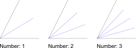
- In the options tool bar enter the length of the bisector(s), starting from
the intersection point of the two lines. In the second text box, choose the
number of angle bisectors you want to create. The default is '1' but you can
also create multiple bisectors as shown here:
- Click the first line entity which limits the angle.
- Click the second line entity with the mouse cursor on that side of the line on which you want to create the angle bisector(s). The preview shows the angle bisector(s) before they are created.
Parallel (with Distance)
Toolbar / Icon:
![]()
![]()
Menu: Draw > Line > Parallel (with Distance)
Shortcuts: L, P | P, A
Commands: lineparallel | lineoffset | parallel | par | lp | pa
Description
With this tool you can create parallels to existing lines (or concentric arcs and circles).
Usage
- Choose the desired line type in the options toolbar.
- Enter the distance of the concentric or parallel entity from the original entity in the options tool bar shown at the top.
- Enter the number of parallel or concentric entities to create in the options tool bar.
- Click the base entity. The parallel or concentric entities are created on that side on which the mouse cursor is located while selecting the entity.
Parallel (through Point)
Toolbar / Icon:
![]()
![]()
Menu: Draw > Line > Parallel (through Point)
Shortcut: L, G
Commands: lineparallelthrough | lineoffsetthrough | parallelthrough | lg
Description
With this tool you can create parallels to existing lines or concentric arcs and circles. The parallel or concentric arc or circle goes through a given point.
Usage
- Choose the desired line type in the options toolbar.
- Enter the number of entities to create in the options tool bar.
- Click the base entity.
- Click the position through which the first parallel or concentric arc or circle runs.
Tangent (Point, Circle)
Toolbar / Icon:
![]()
![]()
Menu: Draw > Line > Tangent (Point, Circle)
Shortcut: L, T, 1
Commands: linetangent | tangent | lt1
Description
Create tangents from a coordinate to an existing arc, circle or ellipse entity with this tool.
Usage
- Choose the desired line type in the options toolbar.
- Use the mouse to specify the location of the start point of the line or enter a coordinate in the command line.
- Click the entity to which you want to create the tangent. Usually, two tangents are possible. When moving the mouse around, you can see a preview of the tangent that will be created.
Tangent (Two Circles)
Toolbar / Icon:
![]()
![]()
Menu: Draw > Line > Tangent (Two Circles)
Shortcut: L, T, 2
Commands: linetangent2 | tangent2 | lt2
Description
Create tangents from one existing arc or circle entity to another one with this tool.
Usage
- Choose the desired line type in the options toolbar.
- Click the first arc or circle entity to which you want to create the tangent.
- Click the second arc or circle entity to which you want to create the tangent. Usually, four tangents are possible. When moving the mouse around, you can see a preview of the tangent that will be created.
Orthogonal / Tangent
Toolbar / Icon:
![]()
![]()
Menu: Draw > Line > Orthogonal / Tangent
Shortcut: L, N
Commands: lineorthogonaltangent | orthotangent
Description
Use this tool to create a line that is orthogonal to another line and tangent to an existing arc, circle or ellipse entity.
Usage
- Choose the desired line type in the options toolbar.
- Click the line entity to which the new line should be orthogonal.
- Click the arc, circle or ellipse entity to which the line should be a tangent. There are two possible solutions. When moving the mouse around, you can see a preview of the tangent that will be created.
Relative Angle
Toolbar / Icon:
![]()
![]()
Menu: Draw > Line > Relative Angle
Shortcut: L, R
Commands: linerelativeangle | lr
Description
Create lines with a relative angle to existing entities with this tool. The existing entity can be a line or an arc / circle. Lines with a relative angle of 0 degrees to an arc are tangents or parallels to tangents. Lines with a relative angle of 90 degrees to an arc or line are orthogonal lines.
Usage
- Choose the desired line type in the options toolbar.
- Enter the relative angle in the options tool bar.
- Click the existing base entity.
- Place the line with the mouse or enter a coordinate in the command line.
Orthogonal
Toolbar / Icon:
![]()
![]()
Menu: Draw > Line > Orthogonal
Shortcut: L, O
Commands: lineorthogonal | lo
Description
This tool lets you create lines orthogonal to an existing base entity. The base entity can be a line, arc or circle.
Usage
- Choose the desired line type in the options toolbar.
- Click the existing base entity.
- Place the line with the mouse or enter a coordinate in the command line.
Freehand Line
Toolbar / Icon:
![]()
![]()
Menu: Draw > Line > Freehand Line
Shortcut: L, F
Commands: linefree | freehand | lf
Description
With this tool you can draw freehand lines. This tool is usually used only
sparingly since technical drawings require absolute accuracy. However, on some
occasions this tool might come in handy, for example for broken edges like
shown here:

Usage
- Place the mouse at the start point of the freehand line, press the left mouse button and keep it down.
- Now move the mouse around to draw the line. At the endpoint of the freehand line, let go of the mouse button.
Arc Tools
Toolbar / Icon:
![]()
Shortcut: W, A
Commands: arcmenu
Center, Point, Angles
Toolbar / Icon:
![]()
![]()
Menu: Draw > Arc > Center, Point, Angles
Shortcut: A, R
Commands: arcc | ar
Description
Draws an arc from its center point, a point on the arc line, start angle and end angle.
Usage
- Choose the direction of the arc in the options toolbar.
- Set the center of the arc using the mouse or enter a coordinate in the command line.
- Define the radius by clicking a point on the arc or by entering a coordinate into the command line. You may also enter the radius in the command line.
- Set the start angle with the mouse or by entering a coordinate or the angle in the command line.
- Set the end angle the same way as the start angle.
- Instead of clicking a point for the radius, start angle and end angle, you can also define these values in the appropriate fields in the options toolbar or enter them directly on your keyboard. If you enter the values directly, there is no need to click into the options toolbar fields or the command line.
2 Points and Radius
Toolbar / Icon:
![]()
![]()
Menu: Draw > Arc > 2 Points and Radius
Shortcut: A, D
Commands: arcradius | ad
Description
Draws an arc using the start point, end point and the radius.
Usage
- Type the arc radius into the options tool bar and choose the arc direction (clockwise or counter-clockwise) and the solution (larger arc or smaller arc).
- Specify the start point of the arc.
- Specify the end point of the arc. If the end point is too far away from the start point for a solution, the closest solution is drawn (a half circle with the given radius and direction).
2 Points and Angle
Toolbar / Icon:
![]()
![]()
Menu: Draw > Arc > 2 Points and Angle
Shortcut: A, 2
Commands: arc2 | a2
Description
Draws an arc using the start point, end point and the included angle.
Usage
- Type the included angle into the options tool bar and choose the arc direction (clockwise or counter-clockwise).
- Specify the start point of the arc.
- Specify the end point of the arc.
2 Points and Length
Toolbar / Icon:
![]()
![]()
Menu: Draw > Arc > 2 Points and Length
Shortcut: A, L
Commands: arclength | al
Description
Draws an arc using the start point, end point and the arc length.
Usage
- Type the arc length into the options tool bar and choose the arc direction (clockwise or counter-clockwise).
- Specify the start point of the arc.
- Specify the end point of the arc. If the end point is too far away from the start point for a solution, nothing is drawn.
2 Points and Height
Toolbar / Icon:
![]()
![]()
Menu: Draw > Arc > 2 Points and Height
Shortcut: A, H
Commands: archeight | ah
Description
Draws an arc using the start point, end point and the arc height.
Usage
- Type the arc height into the options tool bar and choose the arc direction (clockwise or counter-clockwise).
- Specify the start point of the arc.
- Specify the end point of the arc.
3 Points
Toolbar / Icon:
![]()
![]()
Menu: Draw > Arc > 3 Points
Shortcut: A, 3
Commands: arc3 | a3
Description
If you know the start point, the end point and a point in between on the arc line, you can use this tool to draw an arc.
Usage
- Set the start point using the mouse or enter a coordinate in the command line.
- Set the second point to a known point on the arc line.
- Set the endpoint of the arc.
Concentric (with Distance)
Toolbar / Icon:
![]()
![]()
Menu: Draw > Arc > Concentric (with Distance)
Shortcut: A, C
Commands: arcconcentric | ac
Description
With this tool you can create one or multiple concentric arcs with a given distance to an existing arc.
Usage
- Enter the distance of the concentric arc from the original base arc in the options tool bar.
- Enter the number of concentric arcs to create in the options tool bar.
- Click the base arc. The concentric arc(s) are created on that side on which the mouse cursor is located while clicking the base arc.
Concentric (through Point)
Toolbar / Icon:
![]()
![]()
Menu: Draw > Arc > Concentric (through Point)
Shortcut: A, G
Commands: arcconcentricthrough | ag
Description
With this tool you can create concentric arcs that go through a specified point.
Usage
- Enter the number of concentric arcs to create in the options tool bar.
- Click the base arc.
- Click the location through which the first concentric arc should go.
Tangentially Connected
Toolbar / Icon:
![]()
![]()
Menu: Draw > Arc > Tangentially Connected
Shortcut: A, N
Commands: arctangential | an
Description
Draws an arc that connects tangentially to an existing arc or line.
Usage
- Enter the radius of the arc in the options tool bar.
- Click the base entity close to the end where the arc should be connected.
- Specify the end point of the arc.
- Instead of an arc or a line, you can also choose an ellipse arc or spline as base entity.
- Entities inside blocks can be chosen as base entities as well.
- Tick the "Radius" check box in the options toolbar to fix the arc radius to the chosen value. Otherwise, the arc is constructed from the start point to the position of the mouse cursor.
Tangent, Point, Radius
Toolbar / Icon:
![]()
![]()
Menu: Draw > Arc > Tangent, Point, Radius
Shortcut: A, T
Commands: arctangentpointradius | at
Description
Draws an arc with a given radius, tangential to an entity and through a point.
Usage
- Enter the radius in the options tool bar.
- Specify the tangential entity.
- Specify the point on the arc.
- Choose the desired solution by clicking close to it with the left mouse button.
Circle Tools
Toolbar / Icon:
![]()
Shortcut: W, C
Commands: circlemenu
Center, Point
Toolbar / Icon:
![]()
![]()
Menu: Draw > Circle > Center, Point
Shortcut: C, I
Commands: circle | ci
Description
Draws a circle with a given center and a point on the circle line.
Usage
- Set the center of the circle using the mouse or enter a coordinate in the command line.
- Define the radius by clicking a point on the circle line or by entering a coordinate into the command line. You may also enter the radius in the command line.
Center, Radius
Toolbar / Icon:
![]()
![]()
Menu: Draw > Circle > Center, Radius
Shortcut: C, R
Commands: circlecr | cr
Description
This tool lets you create circles with a given center and radius.
Usage
- Enter the radius in the option tool bar.
- Set the center of the circle using the mouse or enter a coordinate in the command line.
Center, Diameter
Toolbar / Icon:
![]()
![]()
Menu: Draw > Circle > Center, Diameter
Shortcut: C, A
Commands: circlediameter | ca
Description
This tool lets you create circles with a given center and diameter.
Usage
- Enter the diameter in the option tool bar.
- Set the center of the circle using the mouse or enter a coordinate in the command line.
2 Points and Radius
Toolbar / Icon:
![]()
![]()
Menu: Draw > Circle > 2 Points and Radius
Shortcut: C, D
Commands: circleradius | cd
Description
Draws a circle from two points on the circle line and a radius.
Usage
- Type the radius into the options tool bar.
- Specify the first point on the circle line.
- Specify the second point on the circle line.
2 Points
Toolbar / Icon:
![]()
![]()
Menu: Draw > Circle > 2 Points
Shortcut: C, 2
Commands: circle2p | c2
Description
Draws a circle with two diametrically opposed points.
Usage
- Set the first point using the mouse or enter a coordinate in the command line.
- Set the second point.
3 Points
Toolbar / Icon:
![]()
![]()
Menu: Draw > Circle > 3 Points
Shortcut: C, 3
Commands: Circle3P | c3
Description
Draws a circle from three known points on the circle line.
Usage
- Set the first point on the circle line using the mouse or enter a coordinate in the command line.
- Set the second point on the circle line.
- Set the third point.
Concentric (with Distance)
Toolbar / Icon:
![]()
![]()
Menu: Draw > Circle > Concentric (with Distance)
Shortcut: C, C
Commands: circleconcentric | cc
Description
With this tool you can create one or multiple concentric circles with a given distance to an existing circle.
Usage
- Enter the distance of the concentric circle from the original base circle in the options toolbar.
- Enter the number of concentric circles to create in the options toolbar.
- Click the base circle. The concentric circle(s) are created on that side on which the mouse cursor is located while clicking the base circle.
Concentric (through Point)
Toolbar / Icon:
![]()
![]()
Menu: Draw > Circle > Concentric (through Point)
Shortcut: C, G
Commands: circleconcentricthrough | cg
Description
With this tool you can create concentric circles that go through a specified point.
Usage
- Enter the number of concentric circles to create in the options toolbar.
- Click the base circle.
- Click the location through which the first concentric circle should go.
Tangent and 2 Points
Toolbar / Icon:
![]()
![]()
Menu: Draw > Circle > Tangent and 2 Points
Shortcut: C, T, 1
Commands: circletangent2p | ct1
Description
Draws a circle that is tangential to an entity and goes through two points.
Usage
- Specify the tangential entity.
- Specify the first point on the circle line.
- Specify the second point on the circle line.
Tangent, Point, Radius
Toolbar / Icon:
![]()
![]()
Menu: Draw > Circle > Tangent, Point, Radius
Shortcut: C, T, P
Commands: circletangentpointradius | ctp
Description
Draws an arc with a given radius, tangential to an entity and through a point.
Usage
- Enter the radius in the options tool bar.
- Specify the tangential entity.
- Specify the point on the arc.
- Choose the desired solution by clicking close to it with the left mouse button.
2 Tangents and Point
Toolbar / Icon:
![]()
![]()
Menu: Draw > Circle > 2 Tangents and Point
Shortcut: C, T, 2
Commands: circletangent2 | ct2
Description
Draws a circle that is tangential to two entities and goes through a point.
Usage
- Specify the first tangential entity.
- Specify the second tangential entity.
- Specify the point on the circle line.
2 Tangents and Radius
Toolbar / Icon:
![]()
![]()
Menu: Draw > Circle > 2 Tangents and Radius
Shortcut: C, T, R
Commands: circletangent2radius | ctr
Description
Draws a circle with a given radius that is tangential to two entities.
Usage
- Type the radius into the options tool bar.
- Specify the first tangential entity.
- Specify the second tangential entity.
Ellipse Tools
Toolbar / Icon:
![]()
Shortcut: W, E
Commands: ellipsemenu
Ellipse (Center, Point, Ratio)
Toolbar / Icon:
![]()
![]()
Menu: Draw > Ellipse > Ellipse (Center, Point, Ratio)
Shortcut: E, P
Commands: ellipse | ep
Description
Draws ellipses with a given center, major axis and minor axis.
Usage
- Set the center of the ellipse using the mouse or enter a coordinate in the command line.
- Define the major axis by clicking the endpoint of the axis, which is a point on the ellipse. You can also enter a coordinate into the command line or enter an angle and major radius in the format @50<30 where 50 is the major radius and 30 is the ellipse angle.
- Define the endpoint of the minor axis which is also a point on the ellipse.
Ellipse Arc
Toolbar / Icon:
![]()
![]()
Menu: Draw > Ellipse > Ellipse Arc
Shortcut: E, A
Commands: ellipsearc | ea
Description
Draws ellipse arcs with a given center, major and minor axis and start and end angles.
Usage
- Set the center of the ellipse using the mouse or enter a coordinate in the command line.
- Define the major axis by clicking the endpoint of the axis, which is a point on the ellipse. You can also enter a coordinate into the command line or enter an angle and major radius in the format @50<30 where 50 is the major radius and 30 is the ellipse angle.
- Define the endpoint of the minor axis which is also a point on the ellipse or enter the length of the minor axis.
- Set the start angle with the mouse or by entering a coordinate or the angle in the command line.
- Set the end angle the same way as the start angle.
Ellipse with Radii
Toolbar / Icon:
![]()
![]()
Menu: Draw > Ellipse > Ellipse with Radii
Shortcut: E, I
Commands: ellipseradii | ei
Description
Draws ellipses with given major and minor radius.
Usage
- Enter the radius in X (major radius), the radius in Y (minor radius) and the ellipse angle in the options toolbar.
- Set the center of the ellipse using the mouse or enter a coordinate in the command line.
Ellipse with Diameters
Toolbar / Icon:
![]()
![]()
Menu: Draw > Ellipse > Ellipse with Diameters
Shortcut: E, D
Commands: ellipsediameters | ed
Description
Draws ellipses with given major and minor diameter (width / height).
Usage
- Enter the diameter in X (major diameter), the diameter in Y (minor diameter) and the ellipse angle in the options toolbar.
- Set the center of the ellipse using the mouse or enter a coordinate in the command line.
Parallel Curve (with Distance)
Toolbar / Icon:
![]()
![]()
Menu: Draw > Ellipse > Parallel Curve (with Distance)
Shortcut: E, C
Commands: ellipseoffset | ec
Description
With this tool you can create one or multiple parallel curves with a given distance to an existing ellipse.
Usage
- Enter the distance of the parallel curves from the original base ellipse in the options toolbar.
- Enter the number of parallel curves to create in the options toolbar.
- Click the base ellipse. The concentric curve(s) are created on that side on which the mouse cursor is located while clicking the base ellipse.
Parallel Curve (through Point)
Toolbar / Icon:
![]()
![]()
Menu: Draw > Ellipse > Parallel Curve (through Point)
Shortcut: E, G
Commands: ellipseoffsetthrough | eg
Description
With this tool you can create curves that are parallel to an ellipse and go through a specified point.
Usage
- Enter the number of parallel curves to create in the options toolbar.
- Click the base ellipse.
- Click the location through which the first parallel curve should go.
Inscribed in Quadrilateral
Toolbar / Icon:
![]()
![]()
Add-on:
![]() QCAD Professional
QCAD Professional
Menu: Draw > Ellipse > Inscribed in Quadrilateral
Shortcut: E, Q
Commands: ellipseinscribedquad | eq
Description
Draws an ellipse that is inscribed in a quadrilateral.
Usage
- Specify the first line of the quadrilateral.
- Specify the second line of the quadrilateral.
- Specify the third line of the quadrilateral.
- Specify the fourth line of the quadrilateral.
Spline Tools
Toolbar / Icon:
![]()
Shortcut: W, N
Commands: splinemenu
Spline (Control Points)
Toolbar / Icon:
![]()
![]()
Menu: Draw > Spline > Spline (Control Points)
Shortcut: S, P
Commands: spline | sp
Description
Draws spline curves from control points. Non-uniform rational B-Splines (NURBS) with homogeneous weighting factors are the only splines that are supported.
Usage
- Choose the degree of the spline in the options tool bar. Supported
degrees are 2 (quadratic b-spline) and 3 (cubic b-spline). The higher the
degree, the 'smoother' the curve becomes.
Note that a quadratic b-spline requires by definition at least 3 control points while a cubic b-spline has at least 4 control points. - Check the 'Closed' check box in the options tool bar if you want to create a closed spline. Closed splines are continuous closed loops.
- Specify the control points. After defining the third (for quadratic b-splines) or fourth (for cubic b-splines) control point, a preview will be shown. You can remove the last control point again by clicking the 'Undo' button in the options tool bar.
- Hit escape or click the right mouse button after setting the last point to confirm the spline shape.
- You can now create another spline or right-click again to terminate the tool.
Example for two open splines (quadratic and cubic):

Example for two closed, periodic splines (quadratic and cubic):

Spline (Fit Points)
Toolbar / Icon:
![]()
![]()
Add-on:
![]() QCAD Professional
QCAD Professional
Menu: Draw > Spline > Spline (Fit Points)
Shortcut: S, L
Commands: splinefit | sl
Description
Draws cubic spline curves from fit points (points on the spline curve).
Usage
- Check the "Closed" check box in the options tool bar if you want to create a closed spline. Closed splines are continuous closed loops.
- Specify the fit points. You can remove the last fit point by clicking the "Undo" button in the options tool bar.
- Hit escape or click the right mouse button after setting the last point to confirm the spline shape.
- You can not create another spline or right-click again to terminate the tool.
Insert Fit Point
Toolbar / Icon:
![]()
![]()
Add-on:
![]() QCAD Professional
QCAD Professional
Menu: Draw > Spline > Insert Fit Point
Shortcut: N, I
Commands: splineinsertfit | ni
Description
With this tool you can insert fit points into existing splines.
Usage
- Click the position on the spline at which a new fit point should be inserted. The fit point is inserted at the point on the spline which is closest to the point that is clicked. If the spline is selected, the new fit points are visualized.
Append Fit Point(s)
Toolbar / Icon:
![]()
![]()
Add-on:
![]() QCAD Professional
QCAD Professional
Menu: Draw > Spline > Append Fit Point(s)
Shortcut: N, A
Commands: splineappend | na
Description
With this tool you can append fit points to existing splines.
Usage
- Click a position near the start of a spline to append fit points at the beginning. Click a position near the end of a spline to append fit points at the end.
- Click the positions of the new fit points.
Remove Fit Point
Toolbar / Icon:
![]()
![]()
Add-on:
![]() QCAD Professional
QCAD Professional
Menu: Draw > Spline > Remove Fit Point
Shortcut: N, R
Commands: splineremovefit | nr
Description
With this tool you can remove fit points from splines.
Usage
- Click the fit point of a spline to remove it.
Simplify
Toolbar / Icon:
![]()
![]()
Add-on:
![]() QCAD Professional
QCAD Professional
Menu: Draw > Spline > Simplify
Shortcut: N, P
Commands: splinesimplify | np
Polyline Tools
Toolbar / Icon:
![]()
Shortcut: W, O
Commands: polylinemenu
Draw Polyline
Toolbar / Icon:
![]()
![]()
Menu: Draw > Polyline > Draw Polyline
Shortcut: P, L
Commands: polyline | pl
Description
This tool lets you draw polylines. A polyline is a continuous line formed
from one or more connected line or arc segments.
Please note that it is almost always more convenient to use the regular
line and arc tools to draw a new polyline. The loosely connected line and arc
segments can then be converted into a polyline entity using the "Create
Polyline from Segments" tool.
Usage
- Specify the start point of the first polyline segment. You can use the mouse or enter a coordinate in the console.
- Specify the endpoint of the first polyline segment.
- Specify the endpoints of additional polyline segments.
If the polyline contains arc segments, you can tick the "Arc" check box and enter the arc radius in the options tool bar when setting the endpoint of an arc segment. The arc will connect smoothly (tangential) to the last segment.
- Tick "Tangential arc" in the options toolbar to create arc segments that are tangentially connected to the last segment.
- Tick the "Radius" checkbox to limit the arc segment radius to the given value. Otherwise the arc segment is constructed from the last segment to the mouse cursor.
- Tick the "Arc angle" checkbox to limit the total arc angle to the given value.
Polyline from Segments
Toolbar / Icon:
![]()
![]()
Add-on:
![]() QCAD Professional
QCAD Professional
Menu: Draw > Polyline > Polyline from Segments
Shortcut: O, G
Commands: polylinefromsegments | og
Description
This tool lets you create polylines from existing segments (lines and arcs that are connected). Connected splines are automatically converted to polylines with arc segments.
Usage
Click one of the segments. A polyline is created from the selected entity
and all line or arc entities that are connected to its end- or start point.
The polyline is created on the same layer with the same attributes as the entity
that is clicked. If that layer is locked, the polyline is created on the current
layer instead.
Polyline from Selection
Toolbar / Icon:
![]()
![]()
Add-on:
![]() QCAD Professional
QCAD Professional
Menu: Draw > Polyline > Polyline from Selection
Shortcut: O, C
Commands: polylinefromselection | oc
Description
This tool lets you create polylines from selected segments (connected lines, arcs and polylines).
Usage
- Select the entities you want to join into polylines.
- Launch this tool.
- All connected entities are joined into a polyline. If not all selected entities are connected, multiple polylines are created.
- The number of polylines created is printed in the command line history.
Partial Polyline Along Selection
Toolbar / Icon:
![]()
![]()
Add-on:
![]() QCAD Professional
QCAD Professional
Menu: Draw > Polyline > Partial Polyline Along Selection
Shortcut: O, L
Commands: polylinealongselection | ol
Description
This tool lets you create polylines along a partial length along a selected path (connected lines, arcs and polylines).
Usage
- Select the entities along which you want to create a polyline.
- Launch this tool.
- Click the start point of the polyline. To start point can be at any position along the selected entities.
- Click the end point of the polyline.
- The polyline is created between the chosen points along the selected entities. Disconnected entities which are not part of the new polyline are deselected.
Insert Node
Toolbar / Icon:
![]()
![]()
Add-on:
![]() QCAD Professional
QCAD Professional
Menu: Draw > Polyline > Insert Node
Shortcuts: O, A | O, I
Commands: polylineinsert | polylineadd | oa | oi
Description
With this tool you can add nodes to existing polylines. Adding a new node to a polyline means to split up one segment into two segments. The two new segments are both straight, even if one of original segments was an arc segment.
Usage
- Specify the segment of the polyline in which you want to add the new node.
- Specify the position of the new node with your mouse or by entering a coordinate.
Append Node(s)
Toolbar / Icon:
![]()
![]()
Add-on:
![]() QCAD Professional
QCAD Professional
Menu: Draw > Polyline > Append Node(s)
Shortcut: O, P
Commands: polylineappend | op
Description
With this tool you can append nodes to the beginning or end of existing polylines. Appending a node to a polyline means to extend it by one segment at the beginning or end.
Usage
- Click the polyline somewhere near the end to which you want to append a node.
- Specify the position of the new node(s) with your mouse or by entering a coordinate.
Delete Node(s)
Toolbar / Icon:
![]()
![]()
Add-on:
![]() QCAD Professional
QCAD Professional
Menu: Draw > Polyline > Delete Node(s)
Shortcut: O, D
Commands: polylinedel | od
Description
Use this tool to remove nodes from existing polylines. This way two segments of a polyline can be joined into one.
Usage
- Specify the polyline from which you want to delete nodes.
- Specify the position of the node that you want to remove.
Remove Nodes between Two Nodes
Toolbar / Icon:
![]()
![]()
Add-on:
![]() QCAD Professional
QCAD Professional
Menu: Draw > Polyline > Remove Nodes between Two Nodes
Shortcut: O, B
Commands: polylinedelbetween | ob
Description
Use this function to delete all nodes between two nodes of an existing polyline.
Usage
- Specify the polyline from which you want to delete segments.
- Specify the position of the first limiting node. That is the node from where you want to start deleting segments. The node itself will not be deleted. In most cases it is appropriate to use the endpoint snap function to specify the node.
- Specify the position of the node where you want to stop deleting. All segments that are between the first node and the second node are removed from the polyline. After the segments are deleted, the two limiting nodes are connected by a straight line segment so the polyline is still one continuous sequence of line segments.
Trim Segments
Toolbar / Icon:
![]()
![]()
Add-on:
![]() QCAD Professional
QCAD Professional
Menu: Draw > Polyline > Trim Segments
Shortcut: O, T
Commands: polylinetrim | ot
Description
Use this function to trim two polyline segments. This means to extend or shorten the two segments, in a way that they meet at one common point.
Usage
- Specify the first polyline segment to trim by clicking it with the mouse.
- Specify the second segment to be trimmed from the same polyline. All segments that are between the first segment and the second segment are removed to keep the polyline a continuous line string.
Relocate Start Point
Toolbar / Icon:
![]()
![]()
Add-on:
![]() QCAD Professional
QCAD Professional
Menu: Draw > Polyline > Relocate Start Point
Shortcut: O, R
Commands: polylinestart | or
Description
Use this tool to choose a new start point for a closed polyline.
Usage
- Click the closed polyline of which the start point should be relocated.
- Click the new position of the start point anywhere along the polyline.
Change Segment Type
Toolbar / Icon:
![]()
![]()
Add-on:
![]() QCAD Professional
QCAD Professional
Menu: Draw > Polyline > Change Segment Type
Shortcut: O, X
Commands: polylinechange | ox
Description
With this tool you can change the type of a polyline segment from an arc to a line and vice versa.
Usage
- Click an existing polyline segment. An arc segment is immediately converted into a line segment. For a line segment, the arc can be defined by clicking a point on the arc.
Arc to Line Segments
Toolbar / Icon:
![]()
![]()
Add-on:
![]() QCAD Professional
QCAD Professional
Menu: Draw > Polyline > Arc to Line Segments
Commands: polylinearctoline
Description
Use this tool to convert all arc segments in polylines into straight line segments.
Usage
- Select the polyline(s) from which you want to convert all segments into line segments.
- Start this tool.
Offset
Toolbar / Icon:
![]()
![]()
Add-on:
![]() QCAD Professional
QCAD Professional
Menu: Draw > Polyline > Offset
Shortcut: O, Q
Commands: polylineequidistant | polylineoffset | oq
Description
This tool lets you create equidistant polylines to existing polylines.
Usage
- Enter the distance of the equidistant and the number of equidistant polylines you want to create at once in the options tool bar.
- Click the original polyline. The equidistant will be created on the side on which you click next to the polyline.
Morph
Toolbar / Icon:
![]()
![]()
Add-on:
![]() QCAD Professional
QCAD Professional
Menu: Draw > Polyline > Morph
Shortcut: O, M
Commands: polylinemorph | om
Description
With this tool, you can morph between two polylines. A number of new intermediate polylines are created. Each intermediate polyline is a mix of the two chosen polylines. With each step of the morphing operation, the position and shape of the first polyline is transformed to be more like the second polyline.
Usage
- Prepare the two polylines.
Usually the two polylines should have the same direction or orientation. For closed polylines, you would typically want the start point to be aligned, so that no rotation occurs while morphing. More complex polylines can be split at sharp corners to maintain the position of those corners throughout the morphing process. - Launch this tool.
- Enter the number of desired steps in the options toolbar.
- Choose the desired easing function in the options toolbar. The normal
easing function is "linear" which interpolates linearly between the two
polylines. Easing functions can be used to create various uneven types of
interpolations.
For example to start morphing at the first polyline, first advancing slowly toward the second polyline and then accelerate toward the second polyline in a quadratic function, choose "in quadratic". - Click the first polyline. You can also select a line, an arc, a circle, an ellipse or a spline.
- Click the second polyline.
- The entered number of intermediate polylines is created.
Example:
In this example, the rounded rectangle is morphed to the ellipse in nine
steps. Both shapes are first converted into polylines (the ellipse is exploded
into a polyline with arc segments). The startpoint of the rounded rectangle is
set to be at the bottom center (1). The start point of the ellipse is set at
its bottom center (2). Both polylines are made counter-clockwise.

Boolean Operations
Toolbar / Icon:
![]()
![]()
Add-on:
![]() QCAD Professional
QCAD Professional
Menu: Draw > Polyline > Boolean Operations
Shortcut: O, W
Commands: polylineboolean | ow
Description
Performs a boolean operation on selected closed polylines. This can be used to combine two polylines (union), to intersect them or to subtract a polyline from another (difference).
Usage
- Select one or multiple closed polylines to unify or intersect. Alternatively, select the polylines from which you want to subtract another polyline
- Start this tool.
- Choose the desired boolean operation in the options toolbar:
-

Intersection (AND): The result is the intersection of all selected polylines. This is a polyline around the area that all polylines have in common. -

Union (OR): The result is the union of all selected polylines. This is a polyline that contains all the selected polylines. -

Difference (NOT): The result is the difference between the union of all selected polylines and the polylines chosen in the next step. -

Exclusive or (XOR): The result is the set of polylines around the area covered by only one original polyline.
-
- If you have chosen the difference mode, choose the polylines to subtract from the selection.
- Choose if holes should be detected automatically. With this option, smaller contours inside other, larger contours are considered to be holes.
- When working with large sets of polylines, switch off the automatic preview to avoid delays while the preview is being updated.
- Click the green tick mark apply button in the options toolbar to apply the operation.
- The selected polylines are still selected, so they can be easily deleted now if desired. The result is added to the current layer.
Simplify
Toolbar / Icon:
![]()
![]()
Add-on:
![]() QCAD Professional
QCAD Professional
Menu: Draw > Polyline > Simplify
Shortcut: O, S
Commands: polylinesimplify | os
Description
Simplifies all selected polylines using the Ramer–Douglas–Peucker algorithm.
Usage
- Select the polyline(s) you want to simplify.
- Start this tool.
- Enter the desired tolerance in the Options toolbar. The tolerance is the maximum distance between the original polyline and the simplified polyline.
Normalize Polylines
Toolbar / Icon:
![]()
![]()
Add-on:
![]() QCAD Professional
QCAD Professional
Menu: Draw > Polyline > Normalize Polylines
Shortcut: O, N
Commands: polylinenormalize | on
Description
Use this tool to automatically remove duplicate nodes from existing polylines.
Usage
- Select the polyline(s) from which you want to delete duplicate nodes.
- Start this tool.
Insert Nodes at Self-Intersections
Toolbar / Icon:
![]()
![]()
Add-on:
![]() QCAD Professional
QCAD Professional
Menu: Draw > Polyline > Insert Nodes at Self-Intersections
Shortcut: O, V
Commands: polylineinsertatselfx | ov
Description
Use this tool to insert nodes at points where the polyline intersects itself.
Logically close Polylines
Toolbar / Icon:
![]()
![]()
Add-on:
![]() QCAD Professional
QCAD Professional
Menu: Draw > Polyline > Logically close Polylines
Shortcut: O, E
Commands: polylinetoclosed | oe
Description
Polylines can be geometrically closed or logically closed. A geometrically closed polyline is essentially an open polyline for which the last node just happens to be at the same position as the first node. In a logically closed polyline with the same shape, the last node is omitted and the information that the polyline is closed is stored in the polyline instead. Logically closed polylines require one node less than geometrically closed ones. Logically closed polylines are often better suitable for further processing (CAM) than geometrically closed ones.
This tool converts all geometrically closed polylines into logically closed polylines.
Logically open Polylines
Toolbar / Icon:
![]()
![]()
Add-on:
![]() QCAD Professional
QCAD Professional
Menu: Draw > Polyline > Logically open Polylines
Shortcut: O, J
Commands: polylinetoopen | oj
Description
This tool converts all logically closed polylines into logically open (but geometrically closed) polylines.
Shape Tools
Toolbar / Icon:
![]()
Shortcut: W, H
Commands: shapemenu
Description
Common Shape Options
Polyline
Shape tools can either create loose lines and arcs or a closed polyline. Tick "Create Polyline" to create a single polyline entity per constructed shape.
Fill
Tick the "Fill" check box to create a solid fill in addition to the boundary of the shape.
Radius
Tick the "Radius" check box to round all corners of the shape with the given radius.
Rectangle
Toolbar / Icon:
![]()
![]()
Menu: Draw > Shape > Rectangle
Shortcut: R, E
Commands: rectangle | linerectangle | rect | re
Description
Use this tool to create rectangular shapes from two diagonally opposite corners.
Usage
- Choose the desired common shape options in the options toolbar.
- Specify the first corner of the rectangle.
- Move the mouse to the second corner and click to specify the second
corner of the rectangle. Alternatively you can enter the coordinate of the
second corner in the command prompt. E.g. to create a rectangle with width 50
and height 25, enter the relative coordinate of the second corner as follows:
@50,25
Rectangle with Size
Toolbar / Icon:
![]()
![]()
Menu: Draw > Shape > Rectangle with Size
Shortcut: R, S
Commands: rectanglesize | linerectanglesize | rs
Description
Use this tool to create rectangular shapes with a given size.
Usage
- Choose the desired common shape options in the options toolbar.
- Enter the size of the rectangle in the options tool bar.
- Choose the reference point you want to use to position the rectangle.
- Specify the position of the rectangle with the mouse or by entering a coordinate in the command line.
Rectangle (3 Points)
Toolbar / Icon:
![]()
![]()
Add-on:
![]() QCAD Professional
QCAD Professional
Menu: Draw > Shape > Rectangle (3 Points)
Shortcut: R, 3
Commands: rectangle3p | linerectangle3p | rect3p | r3
Description
Use this tool to create rectangular shapes from two corners of the first edge and a point on the opposite side.
Usage
- Choose the desired common shape options in the options toolbar.
- Specify the first corner of the rectangle.
- Move the mouse to the second corner and click to specify the second corner of the first edge of the rectangle. This defines the length and rotation angle of the rectangle.
- Click a third point that is on the opposite edge. This defines the width of the rectangle.
Polygon (Center, Corner)
Toolbar / Icon:
![]()
![]()
Menu: Draw > Shape > Polygon (Center, Corner)
Shortcuts: P, G, 1 | H, C
Commands: linepolygon | polygon | pg1
Description
Creates polygons with the center and one corner given.
Usage
- Choose the desired common shape options in the options toolbar.
- Enter the degree of the polygon (number of edges / corners) in the options tool bar. Valid numbers range from 3 to 99.
- Set the center of the polygon using the mouse or enter a coordinate in the command line.
- Set the first corner of the polygon.
Polygon (2 Points of Side)
Toolbar / Icon:
![]()
![]()
Menu: Draw > Shape > Polygon (2 Points of Side)
Shortcuts: P, G, 2 | H, P
Commands: linepolygon2 | polygon2 | pg2
Description
Creates polygons with two corners given.
Usage
- Choose the desired common shape options in the options toolbar.
- Enter the degree of the polygon (number of edges / corners) in the options tool bar. Valid numbers range from 3 to 99.
- Set the first corner of the polygon using the mouse or enter a coordinate in the command line.
- Set the second corner of the polygon.
Polygon (Center, Side)
Toolbar / Icon:
![]()
![]()
Menu: Draw > Shape > Polygon (Center, Side)
Shortcut: P, G, 3
Commands: polygoncs | pg3
Description
Creates polygons with the center and middle point of one side.
Usage
- Choose the desired common shape options in the options toolbar.
- Enter the degree of the polygon (number of edges / corners) in the options tool bar. Valid numbers range from 3 to 99.
- Set the center of the polygon using the mouse or enter a coordinate in the command line.
- Set the middle point of one side of the polygon.
Polygon (Side, Side)
Toolbar / Icon:
![]()
![]()
Menu: Draw > Shape > Polygon (Side, Side)
Shortcut: P, G, 4
Commands: polygonss | pg4
Description
Creates polygons from two opposite corners or sides.
Usage
- Choose the desired common shape options in the options toolbar.
- Enter the degree of the polygon (number of edges / corners) in the options tool bar. Valid numbers range from 3 to 99.
- Choose the option Corner to Corner to define the polygon with two opposite corners.
- Set the first corner or middle of a side of the polygon using the mouse or enter a coordinate in the command line.
- Set the second, opposite corner or middle of a side of the polygon.
Star
Toolbar / Icon:
![]()
![]()
Add-on:
![]() QCAD Professional
QCAD Professional
Menu: Draw > Shape > Star
Shortcut: P, T
Commands: star | pt
Description
Creates stars from a given outer and inner corner.
Usage
- Choose the desired common shape options in the options toolbar.
- Enter the number of outermost corners of the star shape in the options tool bar. Valid numbers range from 3 to 99.
- Tick the option "symmetrical" to create a regular, symmetrical star. Without this option, the inner corner can be placed freely.
- Set the first outer corner of the star using the mouse or enter a coordinate in the command line.
- Set the inner corner of the star.
Hatch Tools
Toolbar / Icon:
![]()
Shortcut: W, X
Commands: hatchmenu
Hatch from Selection…
Toolbar / Icon:
![]()
![]()
Menu: Draw > Hatch > Hatch from Selection…
Shortcut: H, A
Commands: hatch | ha
Description
This tool fills an area surrounded by existing entities with a hatch pattern or a solid color.
Usage
- Prepare the entities that surround the hatching area so they form a
closed contour. The contour must be closed in a way that one entity is
connected to the next one as shown at the right in this example:
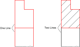
- Select the contour(s) you want to fill. Note that islands inside contours
will get hatched if they are not selected:
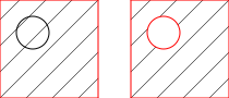
- Launch the hatch tool.
- A dialog for the hatch options is displayed. Choose a hatch pattern, scale factor and a rotation angle for the hatch pattern. If you want to fill the object with a solid color instead of a pattern, check the check box "Solid Fill".
- Click 'OK' to proceed with the hatching. Depending on the complexity of the contour and the scale factor of the chosen pattern, it might take a while to create the hatch.
Hatch from Segments…
Toolbar / Icon:
![]()
![]()
Add-on:
![]() QCAD Professional
QCAD Professional
Menu: Draw > Hatch > Hatch from Segments…
Shortcut: H, S
Commands: hatchsegments | hs
Description
This tool fills an area with a hatch pattern or a solid color. The area is defined by clicking existing entities or untrimmed entity segments which are part of the hatch boundary.
Usage
- Make sure that the area to be filled is enclosed on all sides with entities (e.g. lines, arcs, splines, etc.). The entities do not have to be trimmed to corners for this tool. You can use partial entities or segments of entities as part of the boundary.
- Start this tool.
- Click OK.
- A dialog for the hatch options is displayed. Choose a hatch pattern, scale factor and a rotation angle for the hatch pattern. If you want to fill the object with a solid color instead of a pattern, check the check box "Solid Fill".
- Click all entity segments that are part of the hatch or fill boundary. The selected segments are highlighted. You can also remove a segment from the boundary by clicking it again. The boundary segments do not have to be clicked in any particular order and you can also define islands inside an area.
Viewport Tools
Toolbar / Icon:
![]()
Shortcut: W, T
Commands: viewportmenu
Add Viewport
Toolbar / Icon:
![]()
![]()
Add-on:
![]() QCAD Professional
QCAD Professional
Menu: Draw > Viewport > Add Viewport
Shortcut: V, T
Commands: viewport | vt
Description
Creates a new viewport in a layout block. A viewport is a rectangular area that displays a part of the drawing at a given scale and angle. Viewports can only exist in layout blocks, special blocks dedicated to printing the drawing or parts of it, often along with a border and header.
Usage
- After starting this tool, the model space (main drawing) is shown to define the rectangular area of the drawing the viewport should display.
- Adjust the rotation angle of the viewport in the options toolbar to create a viewport that shows a part of the drawing rotated by a given angle. Note that rotated viewports are not supported in other CAD systems.
- Click the first corner of the viewport area.
- Click the second corner of the viewport area.
- QCAD now switches automatically to a layout block where the viewport can be created. If there are multiple layout blocks and this tool was not started from a layout block, a dialog is shown to let you choose in which layout block you want to place the viewport.
- Adjust the viewport scale in the options toolbar if necessary. If the drawing is larger or much smaller than the available paper size, you will likely want to scale it up or down to fit on the paper.
- Click the center position of the viewport.
The viewport is now added to the layout. To change properties such as scale or rotation angle of the viewport, you can click it to select it and adjust properties using the property editor.
The rectangular border of the viewport is shown if the layer the viewport is on is shown. If the layer the viewport is on is switched off, the border is hidden but the contents of the viewport is still shown. Viewports are typically placed on a dedicated layer (e.g. "viewports") which can be switched off for printing.
Manage Viewport Layers…
Toolbar / Icon:
![]()
![]()
Add-on:
![]() QCAD Professional
QCAD Professional
Menu: Draw > Viewport > Manage Viewport Layers…
Shortcut: V, Y
Commands: viewportlayers | vy
Description
This tool can be used to hide layers in selected viewports.
Usage
- This tool can be started from the context menu of a viewport. Alternatively, select the viewport(s) you want to manage and start this tool from the menu.
- A dialog is shown with a layer list. Click the eye icon next to a layer to toggle the layer on or off for the viewport. This does not affect layers in the main drawing or in other viewports.
- Note that a viewport can only turn additional layers off. It cannot turn a layer on that is off in the main drawing.
Ring
Toolbar / Icon:
![]()
Add-on:
![]() QCAD Professional
QCAD Professional
Menu: Draw > Ring
Shortcut: R, I
Commands: ring | donut | ri
Description
This tool lets you create rings (donuts) with a given center and an inner and outer diameter.
Usage
- Enter the inner and outer diameters in the option tool bar.
- Set the center of the ring using the mouse or enter a coordinate in the command line.
Wipeout
Toolbar / Icon:
![]()
Add-on:
![]() QCAD Professional
QCAD Professional
Menu: Draw > Wipeout
Shortcut: W, P
Commands: wipeout | wp
Description
This tool creates a wipeout entity. A wipeout is a blank area in a drawing that conceals a part of the drawing with the background color. This is typically used to improve the readability of text labels or to hide a part of a drawing that is not relevant.
Usage
- Check the frame option in the options toolbar to create a wipeout with a frame (a line around the boundary).
- Choose the desired tool mode in the options toolbar. The wipeout tool
offers three different modi:
-

Rectangle: creates a rectangular wipeout from two diagonally opposite points.- Click the first and then the second corner of the rectangle.
-

Polygon: creates a polygonal wipeout.- Click the corners of the polygon and click the right mouse button after the last corner has been set. The undo / redo buttons in the options toolbar may be used to correct mistakes.
-

From polyline: creates a wipeout from an existing polyline.- Click a polyline in the drawing to create a wipeout from it. If the option "Delete Polyline" is checked, the original polyline will be deleted. For convenience, the tool also accepts circles, ellipses or splines.
-
Text…
Toolbar / Icon:
![]()
Menu: Draw > Text…
Shortcut: T, E
Commands: text | te
Description
Use this tool to create single line or multi line text entities.
Usage
- After launching the tool, the text dialog is presented in which you can choose the font and enter the text you want to create.
- Choose the font name, text height and initial text attributes in the upper
left area of the dialog.
CAD fonts that are made up of lines and arcs are listed at the top of the font list, TrueType fonts are listed below.
In the "Height" field, enter the height of the text in the unit of your drawing. To choose normal line spacing, enter a line spacing factor or "1". You can increase or decrease the line spacing by entering an alternative value. The value entered is a factor relative to the default (1.0). - Enter the rotation angle for the text. Normal horizontal texts have an angle of 0 degrees and texts that are readable from the right 90 degrees.
- Choose the alignment of the text.
- Check the "Simple Text" check box to create a single line text without any advanced formatting.
- Enter the text you want to create in the large text box.
You can use the various tools above the box to further format the text that you have entered or to paste texts from the clipboard. Use the button at the right to quickly insert symbols or to choose a Unicode character ("Others...").
Note that the font you have chosen might not contain the characters you insert. In that case the characters will not be displayed in the drawing. - Click "OK" to exit the text dialog.
- Use the mouse to specify the location of the text or enter a coordinate in the command line.
- Often, users need to create a number of similar texts. For that reason the text tool does not terminate after creating the first text entity. You can change the text and the text angle in the options tool bar and create other texts with similar settings.
- Right click or press Escape to stop the text tool.
Insert Bitmap…
Toolbar / Icon:
![]()
Menu: Draw > Insert Bitmap…
Shortcut: I, M
Commands: insertbitmap | bitmap | im
Description
Inserts a raster image (bitmap) into the drawing.
Note that the drawing file which is created when saving the drawing,
contains only references to inserted images. It is recommended to keep the
image file and the drawing file in the same folder, so QCAD can find the image
again when the drawing file is loaded later.
Transparent backgrounds are supported for PNG images.
Note that large bitmaps can cause the drawing display to become very
slow.
Usually you will want images to be in the background of other entities.
Please refer to the
'Modify' - 'Send to
back' tool to learn how to do this.
Usage
- Choose the image file which you want to insert.
- Enter the desired height or width for the image in drawing units in the options tool bar.
- Type a rotation angle in the options tool bar.
- Specify the insertion point of the image. That is the left bottom corner of the image.
Trace Bitmap…
Toolbar / Icon:
![]()
Add-on:
![]() QCAD Professional
QCAD Professional
Menu: Draw > Trace Bitmap…
Commands: tracebitmap | trace
Description
This tool traces an inserted image with polylines. This can be used as a means to vectorize in image, for example to quickly trace the outlines of an inserted image from a silhouette.
Usage
- Insert the image you want to trace into your drawing if you have not done so already.
- Select the image and start this tool.
- Choose the desired options in the dialog:
- Monochrome: Enabling this option converts the image to monochrome on the fly before tracing. This can yield better results for silhouette type images that are not completely monochrome already. You can also use this option if you are only interested in the outline of an image with a transparent or white background.
- Alpha Threshold: The maximum alpha (transparency) value of a pixel to be considered white when converting to monochrome. Valid values range from 0 (everything not completely transparent is black) to 255 (everything is white).
- Brightness Threshold: The maximum brightness of a pixel to be considered black. Valid values range from 0 (everything is black) to 255 (everything is white).
- Number of colors: Images are reduced in color before tracing. This number indicates the number of colors to be used for the palette. Lower numbers yield less details or less noise and higher numbers more details or noise.
- You can click the Update button anytime to update a small preview of the image tracing.
- Click OK to trace the image. The polylines are added on the current layer.
Dimension Tools
Toolbar / Icon:
![]()
Shortcut: W, D
Commands: dimensionmenu
Description
Dimensions are used to add measurements to a drawing.
Dimensions typically consist of a text label and some lines and arrows to
indicate the precise location of the measurement. The text label may be
accompanied by tolerance indications or symbols. The options tool bar that is
shown while a dimension is being created supports you to define the dimension
label contents and its tolerances.
Aligned
Toolbar / Icon:
![]()
![]()
Menu: Dimension > Aligned
Shortcut: D, A
Commands: dimaligned | da
Description
Creates aligned dimensions. Aligned dimensions usually measure the length of
an existing line. The dimension line is always parallel to the line between the
two chosen points 1. and 2.:

Usage
- Set the first extension line end point with the mouse or enter a coordinate in the command line.
- Set the second extension line end point.
- Set the position of the dimension line.
Rotated (Linear)
Toolbar / Icon:
![]()
![]()
Menu: Dimension > Rotated (Linear)
Shortcut: D, L
Commands: dimlinear | dimrotated | dl
Description
Creates rotated (linear) dimensions. Linear dimensions are usually used to measure vertical or horizontal distances but can also measure distances with any other angle.
Usage
- Enter the angle of the dimension in the options toolbar.
- Set the first extension line endpoint with the mouse or enter a coordinate in the command line.
- Set the second extension line endpoint.
- Set the position of the dimension line.
Horizontal
Toolbar / Icon:
![]()
![]()
Menu: Dimension > Horizontal
Shortcut: D, H
Commands: dimhor | dimhorizontal | dh
Description
This tool is provided for convenience and behaves essentially like the tool for rotated dimensions. The only difference is that the angle is fixed to 0 degrees (horizontal).
Vertical
Toolbar / Icon:
![]()
![]()
Menu: Dimension > Vertical
Shortcut: D, V
Commands: dimver | dimvertical | dv
Description
This tool is provided for convenience and behaves essentially like the tool for rotated dimensions. The only difference is that the angle is fixed to 90 degrees (vertical).
Baseline
Toolbar / Icon:
![]()
![]()
Add-on:
![]() QCAD Professional
QCAD Professional
Menu: Dimension > Baseline
Shortcut: D, B
Commands: dimbase | baselinedimension | db
Description
Creates a rotated (linear), angular, or ordinate dimension, starting at the
baseline of an existing dimension.

Usage
- Click the base line of an existing linear, angular or ordinate dimension.
- Set the second extension line end point with the mouse or enter a coordinate in the command line. The dimension lines are automatically stacked with a fixed distance between them from each other. You can adjust this distance (the dimension line increment) under Edit > Drawing Preferences > Dimension > Dimension Settings > Dimension line increment. You can also override this setting for individual dimensions in the options toolbar by unchecking Default spacing and entering a value for Spacing.
Continue
Toolbar / Icon:
![]()
![]()
Add-on:
![]() QCAD Professional
QCAD Professional
Menu: Dimension > Continue
Shortcut: D, C
Commands: dimcontinue | continuedimension | dc
Description
Creates a dimension that starts from an extension line of a selected linear,
angular or ordinate dimension.
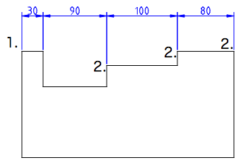
Usage
- Click the base line of an existing linear, angular or ordinate dimension.
- Set the second extension line end point with the mouse or enter a coordinate in the command line.
- Continue to click more extension line end points if desired to create a chain of connected dimensions.
Ordinate (X/Y)
Toolbar / Icon:
![]()
Menu: Dimension > Ordinate (X/Y)
Shortcut: D, O
Commands: dimordinate | do
Description
This tool draws an ordinate dimension. Ordinate dimensions indicate the X-ordinate or Y-ordinate of a feature in the drawing, relative to an origin point.
Usage
- Specify the location of the feature with the mouse or by entering a coordinate.
- Specify the location of the text label and end point of the leader. If the leader is closer to being vertical, the X datum is indicated, if it is closer to being horizontal, the Y datum is indicated.
- The origin of the ordinate dimension is at the absolute zero point. To move the origin by mouse, select the ordinate dimension entity and move the origin with the mouse (drag and drop). To specify a coordinate for the origin, use the property editor.
- Click the mouse arrow symbol in the options tool bar to set the origin
for new ordinate dimensions:

You can then set the new origin location by clicking in the drawing or entering a coordinate in the command line. All new ordinate dimensions created after this measure the distance from that origin.
Leader
Toolbar / Icon:
![]()
![]()
Menu: Dimension > Leader
Shortcuts: D, E | L, D
Commands: leader | dimlea | de | ld
Description
Leaders are arrows that usually point from a text entity to another entity
as shown below. In the example, the text entity "N7" is describing a surface
property by pointing to it with a leader.

Usage
- Set the location where the leader points to or enter a coordinate in the command line.
- Set the location of the next edge of the leader line.
- Set the other edges of the leader line and click the right mouse button or press the Escape key to finish.
Datum
Toolbar / Icon:
![]()
![]()
Add-on:
![]() QCAD Professional
QCAD Professional
Menu: Dimension > Datum
Shortcut: D, T
Commands: datum | dt
Description
Creates a special type of leader typically used to attach a datum
identifier symbol to an edge or surface in a mechanical drawing.

Usage
- Click the start point of the datum leader. That's the point that indicates which feature the datum refers to.
- Set the location of the next edge of the leader line.
- Set the other edges of the leader line and click the right mouse button or press the Escape key to finish.
Tolerance…
Toolbar / Icon:
![]()
![]()
Add-on:
![]() QCAD Professional
QCAD Professional
Menu: Dimension > Tolerance…
Shortcut: T, O
Commands: tolerance | to
Description
Creates a feature control frame typically used for geometric tolerances or
datum identifier symbols.

Usage
- After starting this tool, the Geometric Tolerance dialog is shown.
- Choose the desired tolerance symbol and fill in the tolerance values and datum reference letters as desired. To create a datum identifier symbol (for example [A]), only fill in the field "Datum Identifier".
- Click OK.
- Click the location for the feature control frame.
- Click the right mouse button or press the Escape key to terminate the tool.
Radial
Toolbar / Icon:
![]()
![]()
Menu: Dimension > Radial
Shortcut: D, R
Commands: dimrad | dimradial | dr
Description
Creates radial dimensions for circle or arc entities.

Usage
- Choose a circle or arc entity.
- Set the position of the radial dimension line using the mouse or by entering a coordinate or an angle in the command line.
Diametric
Toolbar / Icon:
![]()
![]()
Menu: Dimension > Diametric
Shortcut: D, D
Commands: dimdia | dimdiametric | dd
Description
Creates diametric dimensions for circle or arc entities.

Usage
- Choose a circle or arc entity.
- Set the position of the diametric dimension line using the mouse or by entering a coordinate or an angle in the command line.
Angular
Toolbar / Icon:
![]()
![]()
Menu: Dimension > Angular
Shortcut: D, N
Commands: dimangular | dn
Description
Creates angular dimensions between two reference lines as shown here:
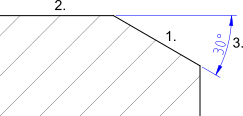
Usage
- Choose the first line entity.
- Choose the second line entity.
- Set the position of the angular dimension arc using the mouse or by entering a coordinate in the command line.
Arc Length
Toolbar / Icon:
![]()
![]()
Add-on:
![]() QCAD Professional
QCAD Professional
Menu: Dimension > Arc Length
Shortcut: D, G
Commands: dimarclength | dg
Description
Creates arc length dimensions as shown here:
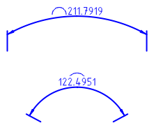
Usage
- Choose the arc entity.
- Set the position of the dimension arc using the mouse or by entering a coordinate in the command line.
The position of the arc symbol can be adjusted in the property editor (property "Arc Symbol Type").
Reset Label Position
Toolbar / Icon:
![]()
![]()
Menu: Dimension > Reset Label Position
Shortcut: D, S
Commands: dimregen | ds
Description
This tool resets the label position of all selected dimension entities and places their label back to their automatically computed position.
Remove Style Overrides
Toolbar / Icon:
![]()
![]()
Add-on:
![]() QCAD Professional
QCAD Professional
Menu: Dimension > Remove Style Overrides
Shortcut: D, X
Commands: dimremovestyle | dx
Description
Removes all dimension style overrides from selected entities. These are dimension style properties that differ from the drawing default.
Modification Tools
Toolbar / Icon:
![]()
Shortcut: W, M
Commands: modifymenu
Move / Copy
Toolbar / Icon:
![]()
![]()
Menu: Modify > Move / Copy
Shortcut: M, V
Commands: move | mv
Description
Moves or copies entities.
Usage
- Select the entities you want to move or copy.
- Launch this tool.
- Set the reference point with the mouse or enter a coordinate in the command line.
- Set the target point. To move the selected entities by a given amount, enter a relative coordinate. For example to move it by 50 drawing units to the right, enter @50,0 in the command line.
- The move dialog is displayed.
To move the entities, choose "Delete Original", to copy them choose "Keep Original". You can also create any given number of copies at once by choosing "Multiple Copies" and entering the number of copies in the text line below. Note that "9" will create 9 copies and keep the original - so there will be 10 instances of the selected entities in the end.
The new entities are placed on the same layer as the originals and have the same attributes. To use the current layer and current attributes instead, tick "Use current layer and attributes". - Click "OK" to move or copy the entities.
Rotate
Toolbar / Icon:
![]()
![]()
Menu: Modify > Rotate
Shortcut: R, O
Commands: rotate | ro
Description
Rotates entities by a given angle around a given center.
Usage
- Select the entities you want to rotate.
- Launch this tool.
- Set the center of the rotation with the mouse or enter a coordinate in the command line.
- The rotate dialog is displayed where you can enter the number of copies
and the rotation angle.
If you want to specify the rotation angle with the mouse cursor, check the mouse cursor button that is displayed beside the angle input:

To delete the original entities, check "Delete Original", to copy them choose "Keep Original". You can also create any given number of copies by choosing "Multiple Copies".
The new entities are placed on the same layer as the originals and have the same attributes. To use the current layer and current attributes instead, tick "Use current layer and attributes". - Click "OK".
- If you have previously chosen to specify the rotation angle by mouse, you now have to first specify a reference point for the rotation and then a target point. The rotation angle is the angle enclosed by the reference point, center of rotation and target point.
Scale
Toolbar / Icon:
![]()
![]()
Menu: Modify > Scale
Shortcut: S, Z
Commands: scale | sz
Description
Scales entities by a given factor towards a given center.
Usage
- Select the entities you want to scale.
- Launch this tool.
- Set the center of the scaling with the mouse or enter a coordinate in the command line.
- The scale dialog is displayed where you can enter the scale factor.
If you want to scale with two different factors in X and Y direction, uncheck the button for proportional scaling:

You can then enter two different scaling factors for X and Y.
If you want to scale the selection by mouse, check the mouse cursor button:

- Click "OK".
- If you have previously chosen to scale the selection by mouse, you now have to specify a reference point and a target point for the scaling operation.
Mirror
Toolbar / Icon:
![]()
![]()
Menu: Modify > Mirror
Shortcut: M, I
Commands: mirror | mi
Description
Mirrors entities along a given axis.
Usage
- Select the entities you want to mirror.
- Launch this tool.
- Specify a first point on the mirror axis with the mouse or enter a coordinate in the command line.
- Specify a second point on the mirror axis.
- The mirror dialog is displayed.
To mirror the entities without keeping the original entities, choose "Delete Original", to copy them choose "Keep Original".
The new entities are placed on the same layer as the originals and have the same attributes. To use the current layer and current attributes instead, tick "Use current layer and attributes". - Click "OK" to mirror the entities.
Flip Horizontal
Toolbar / Icon:
![]()
![]()
Menu: Modify > Flip Horizontal
Shortcut: F, H
Commands: fliphorizontally | fh
Description
This function flips (mirrors) the current selection horizontally.
Flip Vertical
Toolbar / Icon:
![]()
![]()
Menu: Modify > Flip Vertical
Shortcut: F, V
Commands: flipvertically | fv
Description
This function flips (mirrors) the current selection vertically.
Move and Rotate
Toolbar / Icon:
![]()
![]()
Menu: Modify > Move and Rotate
Shortcut: M, R
Commands: moverotate | mr
Description
Moves or copies and simultaneously rotates entities.
Usage
- Select the entities you want to move or copy.
- Launch this tool.
- Enter the rotation angle in the options toolbar
- Set the reference point with the mouse or enter a coordinate in the command line.
- Set the target point.
In the figure below, the two reference points are labeled. The rotation angle in the example is 15 degrees and the number of copies four. This results in a total rotation angle of 60 degrees. - The move and rotate dialog is displayed.
To move the entities, choose "Delete Original", to copy them choose "Keep Original". You can also create any given number of copies at once by choosing "Multiple Copies" and entering the number of copies in the text line below.
The new entities are placed on the same layer as the originals and have the same attributes. To use the current layer and current attributes instead, tick "Use current layer and attributes". - Click "OK" to move and rotate the entities.
Rotate Two
Toolbar / Icon:
![]()
![]()
Menu: Modify > Rotate Two
Shortcut: R, 2
Commands: rotate2 | r2
Description
Rotates and counter-rotates entities. This tool can be useful to rotate entities around a center while maintaining the original orientation of the entities themselves.
Usage
- Select the entities you want to rotate and counter-rotate.
- Launch this tool.
- Set the center for the main rotation with the mouse or enter a coordinate in the command line.
- Set the center of the rotation for the individual objects. This second center of rotation is rotated together with the entities around the first center.
- The rotate two dialog is displayed where you can enter the rotation angle
and counter-rotation angle.
To delete the original entities, check "Delete Original", to copy them choose "Keep Original". You can also create any given number of copies by choosing "Multiple Copies".
The new entities are placed on the same layer as the originals and have the same attributes. To use the current layer and current attributes instead, tick "Use current layer and attributes". - Click "OK" to rotate the entities.

Align Reference Points
Toolbar / Icon:
![]()
![]()
Add-on:
![]() QCAD Professional
QCAD Professional
Menu: Modify > Align Reference Points
Shortcut: A, E
Commands: align | ae
Description
Aligns the selected entities with other, existing entities.
Usage
- Select the entities you want to align.
- Launch this tool.
- Check "Scale" to also scale the selection to fit between the two target points.
- Check "Copy" to create an aligned copy of the selected entities.
- Set the first reference point with the mouse or enter a coordinate in the command line. This point will be aligned with the first target point.
- Set the first target point.
- Set the second reference point to be aligned with the second target point.
- Set the second target point.
- The selection is moved, rotated and optionally scaled in such a way that the two chosen reference points align with the two chosen target points.
Align
Toolbar / Icon:
![]()
![]()
Add-on:
![]() QCAD Professional
QCAD Professional
Menu: Modify > Align
Shortcut: M, A
Commands: alignhv
Description
With this tool, the current selection can be aligned relative to an entity in the drawing, relative to the drawing bounding box or relative to the biggest or smallest entity in the selection.
Usage
- Select the entities you want to align.
- Start the tool.
- In the options toolbar, choose to what you want to align the selection (a picked entity, the whole drawing or a position).
- Choose how you want to align the selection (left, center, right, top, middle, bottom).
- Tick the check box "Treat selection as group" to treat the geometry of the selected entities as one.
- If you have chosen to align to a picked entity, click the entity now.
When aligning to a position, choose the position. When aligning to the whole
drawing, click the tick button in the options toolbar:

Offset (with Distance)
Toolbar / Icon:
![]()
![]()
Menu: Modify > Offset (with Distance)
Shortcut: O, F
Commands: offset | of
Description
With this tool you can create parallels to existing lines (or concentric arcs and circles).
Usage
- Enter the distance of the concentric or parallel entity from the original entity in the options tool bar shown at the top.
- Enter the number of parallel or concentric entities to create in the options tool bar.
- Click the base entity. The parallel or concentric entities are created on that side on which the mouse cursor is located while selecting the entity.
Additional options for the handling of polylines are shown in the options tool bar:
Mode
-
 Polyline Mode: In this mode,
the offset tool offsets entire polylines and other contours at once.
Polyline Mode: In this mode,
the offset tool offsets entire polylines and other contours at once.
If multiple polylines or contours are selected, they are all offset together as shown here:

-
 Segment Mode: In this mode,
individual segments of polylines can be offset.
Segment Mode: In this mode,
individual segments of polylines can be offset.
Offset (through Point)
Toolbar / Icon:
![]()
![]()
Menu: Modify > Offset (through Point)
Shortcut: O, H
Commands: offsetthrough | oh
Description
With this tool you can create parallels to existing lines or concentric arcs and circles. The parallel or concentric arc or circle goes through a given point.
Usage
- Enter the number of entities to create in the options tool bar.
- Click the base entity.
- Click the position through which the first parallel or concentric arc or circle runs.
Trim
Toolbar / Icon:
![]()
![]()
Menu: Modify > Trim
Shortcuts: R, M | X, T
Commands: trim | extend | rm | xt
Description
Trims or extends a line, arc or ellipse to another entity.
Usage
- Choose the limiting entity to which you want to trim or extend one or more other entities.
- Choose the entities that you want to trim to the limiting entity. Often
there are two possibilities for the entity to be trimmed. In the example
below, you might want the top part of the line to remain in the drawing and
the lower part to be trimmed away. In that case you would have to click the
trim entity at the upper part. Always click that part of the entity which you
want to retain.
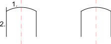
- Right click twice or press Escape twice to terminate the tool.
Trim Both
Toolbar / Icon:
![]()
![]()
Menu: Modify > Trim Both
Shortcut: T, M
Commands: trim2 | extend2 | tm
Description
Trims or extends two lines, arcs or ellipses to their common intersection point.
Usage
- Choose the first entity to be trimmed.
- Choose the second entity to be trimmed.
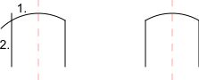
- Right click twice or press Escape twice to terminate the tool.
Lengthen / Shorten
Toolbar / Icon:
![]()
![]()
Menu: Modify > Lengthen / Shorten
Shortcut: L, E
Commands: lengthen | shorten | trimamount | le
Description
This tool can be used to either lengthen or shorten lines or arcs by a given amount.
Usage
- Enter the distance you want to lengthen an entity by in the options tool bar. A positive value lengthens the entity, while a negative value shortens it. E.g. a value of '5' will lengthen the chosen entity by 5 units.
- Choose the entity to be lengthened or shortened somewhere close to the end you want to modify.
- Right click or press the Escape key to terminate the tool.

Stretch
Toolbar / Icon:
![]()
![]()
Menu: Modify > Stretch
Shortcut: S, S
Commands: stretch | ss
Description
This tool stretches contours and dimension entities. This can also be
described as moving all endpoints within a given rectangular or polygonal area.
If there is a selection of entities, this tool only affects the selected
entities. Otherwise, this tool operates on all entities in the given area.

Usage
- Choose in the options toolbar if you want to stretch a rectangular area (rectangle symbol) or a polygonal area (polygon symbol).
- Set the first corner of the stretch area.
- Set the second corner of the stretch area.
- For polygonal areas, set the other corners of the stretch area and right-click the last corner when finished.
- Set the reference point for moving using the mouse or enter a coordinate in the command line.
- Set the target point.
- In the options toolbar you can choose to stretch a rectangular or a polygonal area.
- For polygonal areas, all corner points of the polygon must be clicked. The last corner point is clicked with the right mouse button.
Clip to Rectangle
Toolbar / Icon:
![]()
![]()
Add-on:
![]() QCAD Professional
QCAD Professional
Menu: Modify > Clip to Rectangle
Shortcut: C, L, R
Commands: cliprectangle | cliprect | clr
Description
Clips the current selection to the boundaries of a rectangular area.
Usage
- Select the entities you want to clip.
- Specify the first corner of the rectangular area.
- Move the mouse to the second corner and click to specify the second corner of the rectangular area.
Chamfer / Bevel
Toolbar / Icon:
![]()
![]()
Menu: Modify > Chamfer / Bevel
Shortcut: C, H
Commands: bevel | chamfer | ch
Description
Bevels a corner shaped by two entities. Optionally, the edge entities of the
corner can be trimmed automatically to fit the new shape.

Usage
- Enter the geometry of the bevel in the options tool bar. "Distance 1" is the distance the bevel line will have from the (imaginary) intersection of the two edges (10 in the example shown). "Distance 2" is the same distance for the second edge (20 in the example shown).
- Check "Trim" if you want to trim the entities automatically. If the option is disabled, the two entities will remain untouched.
- Choose the first edge entity (a line or an arc).
- Choose the second entity.
Round
Toolbar / Icon:
![]()
![]()
Menu: Modify > Round
Shortcut: R, N
Commands: round | rn
Description
Rounds the corner of a contour. Optionally, the edge entities of the corner can be trimmed automatically to fit the new shape.
Usage
- Enter the radius of the rounding in the options tool bar (e.g. 5).
- Check "Trim" if you want to trim the entities automatically. If the option is disabled, the two corner entities will remain untouched.
- Choose the first edge entity (a line or arc).
- Choose the second entity.

Divide
Toolbar / Icon:
![]()
![]()
Menu: Modify > Divide
Shortcut: D, I
Commands: divide | di
Description
Divides entities into two separate entities.
Usage
- Choose the entity you want to divide.
- Set the dividing point using the mouse. The dividing point is usually the intersection point with another entity. Choose the intersection snap mode to automatically snap to intersections.
Split Entities
Toolbar / Icon:
![]()
![]()
Add-on:
![]() QCAD Professional
QCAD Professional
Menu: Modify > Split Entities
Shortcut: M, S
Commands: split | ms
Description
This tool splits the selected lines, arcs and circles up into N equally long segments.
Usage
- Select the entities you want to split up.
- Launch this tool.
- Use the options tool bar to specify into how many segments you want to split up the entities. If any circles are selected, you may also enter an angle offset for splitting up these circles.
- Click the button with the tick to split up the selected entities:

Break out Segment
Toolbar / Icon:
![]()
![]()
Menu: Modify > Break out Segment
Shortcut: D, 2
Commands: break | breakout | d2
Description
Divides entities by cutting out a segment that is limited by intersecting entities.
Usage
Choose the entity you want to divide by clicking the segment you want to cut out. The segment is removed automatically if the check box "Remove Segment" is checked. If not, the entity is only cut at the intersections without removing the segment.
- In the options toolbar you can activate the line mode to break out all segments intersected by a line.
- In this mode, you can click a start and an end point to break out all segments that are intersected by the line between the two points.
Break out Manual
Toolbar / Icon:
![]()
![]()
Menu: Modify > Break out Manual
Shortcut: B, 2
Commands: brk | b2
Description
Divides objects by cutting out a segment in between two user defined points.
Usage
- Select the entity you want to break up.
- Click the first point at which the entity is to be divided.
- If the point does not lie on the entity, the separating point is assumed to be the closest point on the entity.
- Click the second point at which the entity is to be divided.
- The segment between the two points is removed if the "Remove Segment" option in the options toolbar is active. Otherwise, the entity is only separated at the given points.
Auto Trim
Toolbar / Icon:
![]()
![]()
Menu: Modify > Auto Trim
Shortcut: A, X
Commands: autotrim | ax
Description
Trims or extends an entity on both sides to the next limiting entities.
Usage
- Choose the entity you want to trim or extend by clicking the segment you want to keep. The entity is automatically trimmed or extended, so that the two end points align with the next two entities.
Break out Gap
Toolbar / Icon:
![]()
![]()
Menu: Modify > Break out Gap
Shortcut: D, 3
Commands: breakoutgap | d3
Description
Breaks out a gap from a line, arc or circle.
Usage
- Pick the entity from which you wish to break out a gap.
- Click the center of the gap on the entity.
Reverse
Toolbar / Icon:
![]()
![]()
Menu: Modify > Reverse
Shortcut: R, V
Commands: reverse | rv
Description
This tool reverses the direction of all selected line, arc and ellipse arc entities. This is mostly useful for drawings that are being prepared for further processing (e.g. CAM).
Edit Text
Toolbar / Icon:
![]()
![]()
Menu: Modify > Edit Text
Shortcut: M, T
Commands: edittext | modifytext | mt
Description
This tool can be used to edit existing text entities.
Usage
- Click the text entity you want to edit.
- The text dialog is shown where you can adjust the text and its attributes.
Note that instead of using this tool, you can also double-click the text entity that you want to edit.
Edit Tolerance
Toolbar / Icon:
![]()
![]()
Add-on:
![]() QCAD Professional
QCAD Professional
Menu: Modify > Edit Tolerance
Shortcut: M, L
Commands: edittolerance | modifytolerance | ml
Description
This tool can be used to edit existing text entities.
Usage
- Click the text entity you want to edit.
- The text dialog is shown where you can adjust the text and its attributes.
Note that instead of using this tool, you can also double-click the text entity that you want to edit.
Edit Hatch
Toolbar / Icon:
![]()
![]()
Menu: Modify > Edit Hatch
Shortcut: M, H
Commands: edithatch | modifyhatch | mh
Description
This tool can be used to edit existing hatch entities.
Usage
- Click the hatch entity you want to edit.
- The hatch dialog is shown where you can adjust the hatch and its attributes.
Note that instead of using this tool, you can also double-click the hatch entity that you want to edit.
Explode
Toolbar / Icon:
![]()
![]()
Menu: Block > Explode
Shortcut: X, P
Commands: explode | xp
Description
Converts block references, polylines, splines, ellipses, texts, dimensions and hatches into more basic entities. Dimensions are split up into lines, triangles and text entities. Text entities are split into polylines (or lines, arcs and splines). Splines are converted into polylines with tangentially connected arc segments. Ellipses are converted into polylines with arc segments. Polylines are split up into loose segments. Hatches are split up into lines. Solid fills are converted to the outline of the solid fill.
Usage
- Select the entities you want to explode.
- Launch this tool to explode the selected entities.
- Repeat step 2 to further break up the selected entities if desired. If an entity cannot be further broken up, it remains unchanged.
Draw Order
Toolbar / Icon:
![]()
Bring to Front
Toolbar / Icon:
![]()
Menu: Modify > Draw Order > Bring to Front
Shortcut: M, F
Commands: tofront | mf
Description
Changes the order in which entities are displayed. Use this tool to bring entities into the foreground if they are hidden behind images, solid fills or other entities.
Usage
- Select the entities to bring into the foreground of the drawing.
- Launch this tool.
Send to Back
Toolbar / Icon:
![]()
Menu: Modify > Draw Order > Send to Back
Shortcut: M, B
Commands: toback | mb
Description
Changes the order in which entities are displayed. Use this tool to send entities that are hiding other entities into the background.
Usage
- Select the entities to move into the background of the drawing.
- Launch this tool.
Reorder
Toolbar / Icon:
![]()
Add-on:
![]() QCAD Professional
QCAD Professional
Menu: Modify > Draw Order > Reorder
Shortcut: M, O
Commands: reorder | mo
Description
With this tool you can reorder entities manually. The draw order of entities is usually not important unless an entity is hiding another one. However, for certain types of further processing (such as CAM), the order of entities can be crucial.
Usage
- To reorder all entities in your drawing, make sure that nothing is selected. Otherwise, select the entities you wish to reorder. Note that if you reorder only selected entities, the order of all other entities remains unchanged. Other entities might be drawn before, after or in between selected entities.
- Click the entity that should be drawn or processed first and subsequently click all entities in the desired order. When the last entity is clicked, the tool automatically terminates. The numerical order of the entities is shown as an overlay while this tool is running.
Order Connected Entities
Toolbar / Icon:
![]()
Add-on:
![]() QCAD Professional
QCAD Professional
Menu: Modify > Draw Order > Order Connected Entities
Shortcut: M, C
Commands: orderconnected | mc
Detection Tools
Toolbar / Icon:
![]()
Detect Duplicates
Toolbar / Icon:
![]()
Add-on:
![]() QCAD Professional
QCAD Professional
Menu: Modify > Detection > Detect Duplicates
Shortcut: M, D
Commands: duplicates
Description
This tool can be used to find, select and optionally delete identical entities in the current drawing.
Usage
- After launching the tool, the options tool bar displays controls to enter tolerance values for the comparison of entities. Adjust these if appropriate.
- Tick the option "Ignore Layer" if you want two identical entities on different layers to be considered equal.
- Click the refresh button to run the search again if you have made any
adjustments to the tolerances and the "Auto" check box is not checked:

If the "Auto" check box is checked, the search for duplicates is automatically repeated if you change any of the options. - Click the delete button if you wish to delete the selected duplicates:

- Click the close button to terminate this tool:

Detect Zero-Length Entities
Toolbar / Icon:
![]()
Add-on:
![]() QCAD Professional
QCAD Professional
Menu: Modify > Detection > Detect Zero-Length Entities
Shortcut: M, Z
Commands: zerolength | zero
Description
This tool can be used to find, select and optionally delete very small entities (length almost 0) in the current drawing.
Usage
- After launching the tool, the options tool bar displays controls to enter tolerance values that are used to detect zero length entities. Adjust these if appropriate.
- Click the refresh button to run the search again if you have made any
adjustments to the tolerances and the "Auto" check box is not checked:

If the "Auto" check box is checked, the search for duplicates is automatically repeated if you change any of the options. - Click the delete button if you wish to delete the selected zero length entities:

- Click the close button to terminate this tool:

Projection Tools
Toolbar / Icon:
![]()
Shortcut: W, J
Commands: projectmenu
Orthographic Projection (Cylindrical)
Toolbar / Icon:
![]()
Add-on:
![]() QCAD Professional
QCAD Professional
Menu: Modify > Projection > Orthographic Projection (Cylindrical)
Shortcut: P, R
Commands: orthocylindrical | orthocyl | pr
Description
Creates an orthographic projection of the selected entities onto a cylindric surface. This is typically used to create the edge of a drilling in a side view of a cylinder as shown in the figure below on the right.
Usage
- Select the entities you want to project. In the example below, that is the circle at the left.
- Start this tool.
- Click the start point of the unprojected cylinder axis. In the example below that is at the top center of the cylinder at the left.
- Click the end point of the cylinder axis.
- Click the reference point. The reference point in the selection will be used to place the projected entities into the side view.
- Adjust the parameters in the options tool bar as desired.
The cylinder diameter is the diameter of the cylindric shape we are projecting onto.
The cylinder rotation is the rotation of the projected entities around the cylinder axis. Typically 90 or -90 degrees.
Since the resulting shapes are likely neither lines or arcs, projected entities are split up into polylines with small segments. You can adjust the segment length used in the options tool bar.
The clipping option can be enabled to automatically hide the part of the projected shape that would lay behind the X/Y plane. - Click the target point to position the projection.

Isometric Projection
Toolbar / Icon:
![]()
Menu: Modify > Projection > Isometric Projection
Shortcut: P, J
Commands: isometric | pj
Description
This tool creates isometric projections (and other types of projections) of the current selection in the drawing.
Usage
- Select the entities you want to project.
- Launch this tool.
- Choose a projection type and a viewing direction for the projection in the options tool bar.
- Set the reference point for the projection. This is the point you will use to position the projection in the next step.
- Move the mouse cursor to the position where you want to create the projection and click to set the position.
Isometric Projection (Cylindrical)
Toolbar / Icon:
![]()
Add-on:
![]() QCAD Professional
QCAD Professional
Menu: Modify > Projection > Isometric Projection (Cylindrical)
Shortcut: P, C
Commands: isometriccylindrical | isocyl | pc
Description
This tool creates an isometric projection of the current selection onto a cylindric surface.
Usage
- Select the entities you want to project.
- Launch this tool.
- Choose a viewing direction for the projection in the options tool bar.
- Enter the diameter of the cylinder in the options tool bar.
- Enter the rotation of the projected entities around the cylinder axis in degrees in the options tool bar.
- Set the start point of the unprojected cylinder axis.
- Set the end point of the cylinder axis.
- Set the reference point for the projection. This is the point you will use to position the projection in the next step.
- Move the mouse cursor to the position where you want to create the projection and click to set the position. Before setting the definitive position, you might still want to adjust the cylinder diameter, rotation angle and viewing direction in the options tool bar, until the preview matches your expectations.
Matrix Transformation
Toolbar / Icon:
![]()
![]()
Add-on:
![]() QCAD Professional
QCAD Professional
Menu: Modify > Projection > Matrix Transformation
Shortcut: M, X
Commands: matrixtransform | mx
Description
This tool transforms the selection using an arbitrary user defined transformation matrix.
Usage
- Select the entities you want to transform.
- Launch this tool.
- Enter the transformation matrix in the options tool bar.
- For convenience, you may additionally enter a factor that is applied to each element of the matrix.
- Set the reference point for the transformation. This is the point you will use to position the transformed entities in the next step.
- Move the mouse cursor to the position where you want to create the transformation and click to set the position. Before setting the definitive position, you might still want to adjust the transformation matrix in the options tool bar, until the preview matches your expectations.
Property Painter
Toolbar / Icon:
![]()
![]()
Add-on:
![]() QCAD Professional
QCAD Professional
Menu: Modify > Property Painter
Shortcut: P, I
Commands: propertypainter | pi
Description
This tool applies properties of a chosen entity to the current selection. Properties that can be copied for all entities are:
- Layer
- Color
- Lineweight
- Linetype
- Custom properties
- Text font
- Text height
- Bold property
- Italic property
- Solid property
- Pattern
- Scale
- Angle
Usage
- Select the target entities to which you want to apply the properties.
- Start this tool.
- Choose in the options toolbar which properties you want to copy.
- Click the entity from which the properties are copied.
Snap Tools
Toolbar / Icon:
![]()
Commands: snapmenu
Free
Toolbar / Icon:
![]()
![]()
Menu: Snap > Free
Shortcut: S, F
Commands: snapfree | sf
Description
Allows free positioning using the mouse. Note that this is almost never the recommended way of setting coordinates in a CAD system except for drawing freehand lines.
Grid
Toolbar / Icon:
![]()
![]()
Menu: Snap > Grid
Shortcut: S, G
Commands: snapgrid | sg
Description
Snaps to grid points.
End
Toolbar / Icon:
![]()
![]()
Menu: Snap > End
Shortcut: S, E
Commands: snapend | se
Description
Snaps to end points of lines, arcs polyline segments, splines, ellipse arcs and to points.

On Entity
Toolbar / Icon:
![]()
![]()
Menu: Snap > On Entity
Shortcut: S, T
Commands: snaponentity | st
Description
Snaps to the closest point on an entity.

Perpendicular
Toolbar / Icon:
![]()
![]()
Menu: Snap > Perpendicular
Shortcut: S, U
Commands: snapperpendicular | su
Description
Snaps to the perpendicular point on a line, arc, circle or ellipse. This only applies when drawing lines.
Tangential
Toolbar / Icon:
![]()
![]()
Menu: Snap > Tangential
Shortcut: S, B
Commands: snaptangential | sb
Description
Snaps to the point of tangency on an arc, circle or ellipse. This only applies when drawing lines. The snap point is the tangent point of an imaginary line from the relative zero point, tangential to the clicked arc or circle.
Center
Toolbar / Icon:
![]()
![]()
Menu: Snap > Center
Shortcut: S, C
Commands: snapcenter | sc
Description
Snaps to the center of arcs, circles and ellipses as well as to the middle
of lines and to points.

Reference
Toolbar / Icon:
![]()
![]()
Menu: Snap > Reference
Shortcut: S, R
Commands: snapreference | sr
Description
Snaps to reference points. Reference points are the blue points that are shown when an entity is selected. This is particularly useful to snap to reference points of circles and arcs, for example when drawing center lines.

Middle
Toolbar / Icon:
![]()
![]()
Menu: Snap > Middle
Shortcut: S, M
Commands: snapmiddle | sm
Description
Snaps to middle points of lines and arcs and to point entities. Note that the middle of an arc is at the middle of the arc line on the arc, not at its center.

Middle Manual
Toolbar / Icon:
![]()
![]()
Menu: Snap > Middle Manual
Shortcut: S, N
Commands: snapmiddlemanual | sn
Description
This tool allows you to snap to a point that is in the middle between two points. This is most commonly used to snap to the center of a rectangle or polygon by choosing two diagonally opposite corners.
Usage
- After activating this snap tool, specify the first of the two points that define the middle point. For example one corner of a rectangle.
- Click the second of the two points, for example the diagonally opposite corner of the rectangle.

Distance
Toolbar / Icon:
![]()
![]()
Menu: Snap > Distance
Shortcut: S, D
Commands: snapdistance | sd
Description
Snaps to points with a given distance to the end point of lines or arcs.
Usage
- Enter the distance into the options toolbar.
- Move the cursor to the entity along which the distance should be measured.
- When the desired position / preview is shown, click the left mouse button to set the coordinate.

Distance Manual
Toolbar / Icon:
![]()
![]()
Menu: Snap > Distance Manual
Shortcut: S, H
Commands: snapdistancemanual | sh
Description
This tool allows you to snap to a point that lays on the imaginary
line between two points at a given distance from the first point.
This snap tool does not restrict the distance, percentage or fraction
entered. Entering a distance greater than the distance between the two points,
a percentage greater than 100 or a fraction greater than 1.0 will allow you
to snap to a point beyond the second point.
Negative values can be entered to snap to points beyond the first point.
Fractions may be entered as decimal numbers (0.5, 0.7) or as fractions
(1/7, 3/11).
Usage
- After activating this snap tool, choose "Distance", "Percentage", or "Fraction" and enter the desired value in the options tool bar.
- Specify the first point. That is the point to measure the distance from.
- Click the second point.

Intersection
Toolbar / Icon:
![]()
![]()
Menu: Snap > Intersection
Shortcut: S, I
Commands: snapintersection | si
Description
Snaps to intersection points between entities.

Intersection Manual
Toolbar / Icon:
![]()
![]()
Menu: Snap > Intersection Manual
Shortcut: S, Y
Commands: snapintersectionmanual | sy
Description
Sometimes the intersection snap mode cannot be used to snap to an intersection point because the intersection point lays outside one or both of the entities. This snap tool lets you explicitly specify two intersecting entities and snap to their intersection point.
Usage
- After activating this snap tool, click the first of the two intersecting entities.
- Click the second of the two intersecting entities. If two intersection points are possible, make sure to click the second entity somewhere closer to the intersection point you want to snap to.

Auto
Toolbar / Icon:
![]()
![]()
Menu: Snap > Auto
Shortcut: S, A
Commands: snapauto | sa
Description
The auto snap tool snaps to the closest intersection point, end point,
middle point, perpendicular point, reference point, grid point or point on an
entity in that order of priority.
The types of reference points the auto snap tool snaps to can be configured
under Edit > Application Preferences > Snap > Auto snap.
Coordinate
Toolbar / Icon:
![]()
![]()
Menu: Snap > Coordinate
Shortcut: S, X
Commands: snapcoordinate | sx
Description
Defines a point by entering an absolute or relative Cartesian coordinate.
Usage
- Start this tool when you have to specify a point and want to do so by entering a pair of coordinates (x/y).
- Enter the coordinates in the options tool bar and choose if they are absolute coordinates or a relative ones (relative to the relative zero point).
- Click the OK button or press Enter to confirm the input and set the
coordinates:

Polar Coordinate
Toolbar / Icon:
![]()
![]()
Menu: Snap > Polar Coordinate
Shortcut: S, O
Commands: snappolar | so
Description
Defines a point by entering an absolute or relative polar coordinate.
Usage
- Start this tool when you have to specify a point and want to do so by entering a polar coordinate.
- Enter the polar coordinate (radius and angle) in the options tool bar and choose if it is an absolute coordinate or a relative one (relative to the relative zero point).
- Click the OK button or press Enter to confirm the input and set the
coordinate:

X/Y from Points
Toolbar / Icon:
![]()
![]()
Menu: Snap > X/Y from Points
Shortcut: P, X
Commands: px
Description
This snap tool can be used to extract one coordinate (e.g. X) from the
location of one existing entity and the other coordinate (e.g. Y) from the
location of another object.
This can for example be used to locate the center of a rectangle.
This concept is also referred to as 'combining coordinates', 'point
filtering' or 'coordinate filtering'.
Usage
- When specifying a position, start this tool.
- Click a position in the drawing to lock the X coordinate at that position.
- Click a position in the drawing to lock the Y coordinate at that position.
Y/X from Points
Toolbar / Icon:
![]()
![]()
Menu: Snap > Y/X from Points
Shortcut: P, Y
Commands: py
Description
This tool works the same way as the tool X/Y from Points, but with opposite order of coordinate input.
Center of Selection
Toolbar / Icon:
![]()
![]()
Menu: Snap > Center of Selection
Shortcut: S, K
Commands: snapselectioncenter | sk
Description
Snaps to the center of the current selection. This is the point at the center between the leftmost and the rightmost edge in X direction and the lowermost and the uppermost edge in Y direction of the selection.
Restrictions Off
Toolbar / Icon:
![]()
![]()
Menu: Snap > Restrictions Off
Shortcut: E, N
Commands: restrictoff | en
Description
Switches off all snap restrictions.
Restrict Orthogonally
Toolbar / Icon:
![]()
![]()
Menu: Snap > Restrict Orthogonally
Shortcut: E, O
Commands: restrictorthogonal | eo
Description
Restricts the cursor vertically or horizontally to the same X or Y position as the relative zero point.
Restrict Horizontally
Toolbar / Icon:
![]()
![]()
Menu: Snap > Restrict Horizontally
Shortcut: E, H
Commands: restricthorizontal | eh
Description
Restricts the cursor horizontally to the same Y position as the relative zero point.
Restrict Vertically
Toolbar / Icon:
![]()
![]()
Menu: Snap > Restrict Vertically
Shortcut: E, V
Commands: restrictvertical | ev
Description
Restricts the cursor vertically to the same X position as the relative zero point.
Restrict Angle or Length
Toolbar / Icon:
![]()
![]()
Menu: Snap > Restrict Angle or Length
Shortcut: E, L
Commands: restrictanglelength | el
Description
Restricts the cursor movement by angle and distance in relation to the relative zero point.
Set Relative Zero
Toolbar / Icon:
![]()
![]()
Menu: Snap > Set Relative Zero
Shortcut: R, Z
Commands: setrelativezero | rz
Description
Lets you set a new location for the relative zero point.
Usage
- Click the new location of the relative zero point.
Lock Relative Zero
Toolbar / Icon:
![]()
![]()
Menu: Snap > Lock Relative Zero
Shortcut: R, L
Commands: lockrelativezero | rl
Description
When enabled, this switch locks the position of the relative zero point. This means it does not move around automatically but you can still move it manually using the tool to set the position of the relative zero point.
Lock Snap
Toolbar / Icon:
![]()
![]()
Add-on:
![]() QCAD Professional
QCAD Professional
Menu: Snap > Lock Snap
Shortcut: S, Q
Commands: locksnap | sq
Description
When enabled, this switch keeps the current snap tool active even when a new tool is started.
Information Tools
Toolbar / Icon:
![]()
Shortcut: W, I
Commands: infomenu | informationmenu | measuringmenu
Description
The tools in the Info menu can be used to measure distances, areas and query
other information from the drawing.
Some of the tools offer an option to add the measured result to the drawing
as text if desired.
Position
Toolbar / Icon:
![]()
![]()
Menu: Info > Position
Shortcut: I, O
Commands: infopos | io
Description
This tool outputs the absolute, Cartesian coordinates of chosen points in the drawing.
Relative Position
Toolbar / Icon:
![]()
![]()
Menu: Info > Relative Position
Shortcut: I, V
Commands: infoposrel | iv
Description
This tool outputs the relative, Cartesian coordinates of chosen points in the drawing.
Polar Position
Toolbar / Icon:
![]()
![]()
Menu: Info > Polar Position
Shortcut: I, L
Commands: infopospol | il
Description
This tool outputs the absolute, polar coordinates of chosen points in the drawing.
Relative Polar Position
Toolbar / Icon:
![]()
![]()
Menu: Info > Relative Polar Position
Shortcut: I, T
Commands: infopospolrel | it
Description
This tool outputs the relative, polar coordinates of chosen points in the drawing.
Distance Point to Point
Toolbar / Icon:
![]()
![]()
Menu: Info > Distance Point to Point
Shortcut: I, P
Commands: infodist | ip
Description
This tool measures the exact distance between two points given by the user.
Usage
- Use the mouse to specify the location of the first point or enter a coordinate in the command line.
- Specify the second point.
- The measured distance is printed on screen and in the command line.
Distance Entity to Point
Toolbar / Icon:
![]()
![]()
Menu: Info > Distance Entity to Point
Shortcut: I, E
Commands: infodistep | ie
Description
This tool measures the exact distance between an entity and a point given by the user.
Usage
- Specify the entity.
- Use the mouse to specify the location of the point or enter a coordinate in the command line.
- The measured distance is printed on screen and in the command line.
Distance Entity to Entity
Toolbar / Icon:
![]()
![]()
Menu: Info > Distance Entity to Entity
Shortcut: I, N
Commands: infodistee | in
Description
This tool measures the exact distance between an entity and a point given by the user.
Usage
- Specify the entity.
- Use the mouse to specify the location of the point or enter a coordinate in the command line.
- The measured distance is printed on screen and in the command line.
Angle
Toolbar / Icon:
![]()
![]()
Menu: Info > Angle
Shortcut: I, A
Commands: infoangle | ia
Description
This tool measures the angle between two given lines.
Usage
- Specify the first line.
- Specify the second line.
- The measured angle (in degrees) is printed on screen and in the command line.
Total Length of Selection
Toolbar / Icon:
![]()
![]()
Add-on:
![]() QCAD Professional
QCAD Professional
Menu: Info > Total Length of Selection
Shortcut: I, S
Commands: infosum | is
Description
This tool calculates the total length of a selection of entities.
Usage
- Select the entities you want to measure the total length from.
- Start the tool.
- The total length of the selected entities is printed in the command line.
Polygonal Area
Toolbar / Icon:
![]()
![]()
Menu: Info > Polygonal Area
Shortcut: I, R
Commands: infoarea | ir
Description
This tool measures the area covered by a polygon and its circumference.
Usage
- Specify the first point of the area.
- Specify the other points that define the area and right click when you are finished.
- The measured area is printed on screen and in the command line. The circumference is also printed in the command line.
Arc/Circle/Ellipse Area
Toolbar / Icon:
![]()
![]()
Menu: Info > Arc/Circle/Ellipse Area
Shortcut: I, C
Commands: acearea | ic
Description
Author: Robert S.
This command calculates the area of arcs, circles, ellipses and elliptical arcs, and optionally adds the information to the current layer of a drawing. If you select any other type of entity a warning is shown in the command line.
For arcs, there are two options for calculating areas, namely Segment or Sector. The area of a segment (or slice) is the area bound by the arc and two lines drawn from the arc's startpoint and endpoint to the arc's centre. The area of a sector is the area bound by the arc and a chord drawn from the arc's startpoint to the endpoint.

Figure 1: a segment (slice) and sector.
Options
This command has the standard "Add measurement to drawing" and "Text Height" options.

Figure 2: Standard Info options
Whether this is off or not, when you click on an arc, circle, ellipse or elliptical arc, the information is displayed in the command line widget.
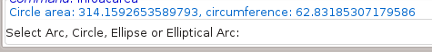
Figure 3: Info displayed in command line
(Note: Every time you start an info command the "Add measurement to drawing" checkbox is always unchecked. You must remember to switch it on if you want the info added to the drawing).
It also adds the following options.
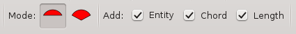
Figure 4: Added options
Mode:
The mode only applies to arcs.
![]()
Sector: This mode returns the area of the sector. This is useful when
used in conjunction with the "Polygonal Area" command.
![]() Segment: This mode returns the area of the segment.
Segment: This mode returns the area of the segment.
Add:
Entity: This selects whether you want to add a copy of the measured entity to the current layer of the drawing.
Chord: This selects if you want the chord (sector), or radius lines (segment), added to the drawing.
Length: By default the area is always printed on the drawing. This option selects whether you want extra information added to the drawing.
For circles and full ellipses the extra information is the circumference. This uses the centre point as the lower left corner for the added text.
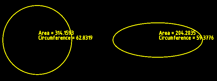
For circular arcs the extra information is the length of the arc and the length of the chord (in sector mode), or the radius (in segment mode).
For ellipses the extra information is the length of the arc and the length of the chord (in sector mode), or the distance from the centre point to the startpoint of the arc, followed by the distance from the centre point to the endpoint of the arc (in segment mode).
The lower left corner for the added text is the endpoint of the arc.
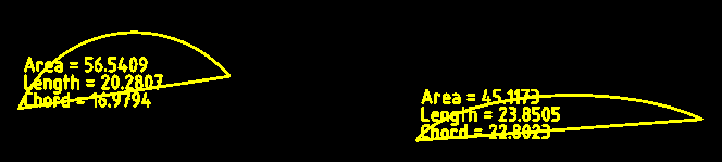
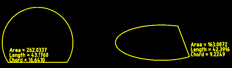
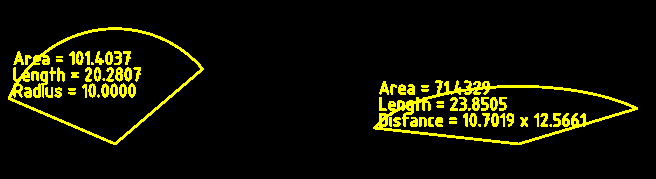
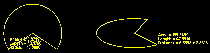
Polyline Area
Toolbar / Icon:
![]()
![]()
Add-on:
![]() QCAD Professional
QCAD Professional
Menu: Info > Polyline Area
Shortcut: I, I
Commands: infopolylinearea | ii
Description
This tool measures the area of a polyline.
Usage
- Specify the polyline entity.
- The measured area is printed on screen and in the command line.
Layer Tools
Toolbar / Icon:
![]()
Shortcut: W, Y
Commands: layermenu
Description
The tools in the Layer menu can be used to add, modify and delete layers. Some of the tools are also available as tool buttons at the top of the layer list.
Toggle Visibility
Toolbar / Icon:
![]()
Menu: Layer > Toggle Visibility
Shortcut: Y, V
Commands: layertogglevisibility | yv
Description
This tool toggles the visibility of the current layer. You may also toggle layers by clicking on the eye icon beside the layer name in the layer list. A black eye icon means that the layer is visible, a gray icon that the layer is hidden.
Toggle Frozen Status
Toolbar / Icon:
![]()
![]()
Add-on:
![]() QCAD Professional
QCAD Professional
Menu: Layer > Toggle Frozen Status
Shortcut: Y, F
Commands: layertogglefrozen | yf
Description
This tool toggles the frozen status of the current layer. You may also toggle the frozen status of layers by clicking on the ice or sun icon beside the layer name in the layer list.
Note that block references on frozen layers are not shown while block references on layers that are off are still shown (provided that they contain any entities on layers which are on and not frozen).
Toggle Lock Status
Toolbar / Icon:
![]()
Menu: Layer > Toggle Lock Status
Shortcut: Y, L
Commands: layertogglelock | yl
Description
This tool toggles the locked status of the current layer. You may also toggle the locked status of layers by clicking on the lock icon beside the layer name in the layer list.
Entities on locked layers cannot be selected, deleted or modified.
Show Only Active
Toolbar / Icon:
![]()
![]()
Menu: Layer > Show Only Active
Shortcut: Y, O
Commands: layershowactive | yo
Description
This tool hides all layers except for the selected (active) layer in the layer list.
Show All Layers
Toolbar / Icon:
![]()
![]()
Menu: Layer > Show All Layers
Shortcut: Y, S
Commands: layershowall | ys
Description
This tool can be used to conveniently show all layers at once. This can be useful while working with a drawing with many layers.
Hide All Layers
Toolbar / Icon:
![]()
![]()
Menu: Layer > Hide All Layers
Shortcut: Y, H
Commands: layerhideall | yh
Description
This tool can be used to conveniently hide all layers at once. This can be useful while working with a drawing with many layers.
Thaw All Layers
Toolbar / Icon:
![]()
![]()
Add-on:
![]() QCAD Professional
QCAD Professional
Menu: Layer > Thaw All Layers
Shortcut: Y, W
Commands: layerthawall | yw
Description
This tool can be used to conveniently thaw all layers at once. This can be useful while working with a drawing with many layers.
Freeze All Layers
Toolbar / Icon:
![]()
![]()
Add-on:
![]() QCAD Professional
QCAD Professional
Menu: Layer > Freeze All Layers
Shortcut: Y, Z
Commands: layerfreezeall | yz
Description
This tool can be used to conveniently hide (freeze) all layers at once. This can be useful while working with a drawing with many layers.
Lock All Layers
Toolbar / Icon:
![]()
![]()
Menu: Layer > Lock All Layers
Shortcut: Y, K
Commands: layerlockall | yk
Description
This tool can be used to conveniently lock all layers at once.
Unlock All Layers
Toolbar / Icon:
![]()
![]()
Menu: Layer > Unlock All Layers
Shortcut: Y, N
Commands: layerunlockall | yn
Description
This tool can be used to conveniently unlock all layers at once.
Add Layer…
Toolbar / Icon:
![]()
![]()
Menu: Layer > Add Layer…
Shortcut: Y, A
Commands: layeradd | addlayer | ya
Description
This command creates a new layer. The layer dialog is shown where you can specify the name for the new layer and adjust its attributes.
QCAD Professional
In addition, you can choose if objects on this layer can be snapped to and
if this layer should be printed.
A layer can be made a sub-layer of a parent layer. The layer list will then show a tree structure of hierarchical layers.
Add Sublayer…
Toolbar / Icon:
![]()
Add-on:
![]() QCAD/CAM
QCAD/CAM
Menu: Layer > Add Sublayer…
Shortcut: Y, U
Commands: layeraddsub | yu
Set Parent Layer…
Toolbar / Icon:
![]()
![]()
Add-on:
![]() QCAD Professional
QCAD Professional
Menu: Layer > Set Parent Layer…
Shortcut: Y, X
Commands: layersetparent | setparentlayer | yx
Create Layer from Selection…
Toolbar / Icon:
![]()
![]()
Add-on:
![]() QCAD Professional
QCAD Professional
Menu: Layer > Create Layer from Selection…
Shortcut: Y, T
Commands: layerfromselection | yt
Move Selection to Current Layer
Toolbar / Icon:
![]()
![]()
Add-on:
![]() QCAD Professional
QCAD Professional
Menu: Layer > Move Selection to Current Layer
Shortcut: Y, J
Commands: layertocurrent | yj
Duplicate Layer…
Toolbar / Icon:
![]()
![]()
Add-on:
![]() QCAD Professional
QCAD Professional
Menu: Layer > Duplicate Layer…
Shortcut: Y, Y
Commands: layercopy | layerduplicate | yy
Description
This tool creates a copy of the layer currently selected in the layer list. A dialog is shown that allows you to enter a name for the new layer.
Delete Layer(s)
Toolbar / Icon:
![]()
![]()
Menu: Layer > Delete Layer(s)
Shortcut: Y, R
Commands: layerdelete | yr
Description
You can delete the currently selected layer from the layer list with this
command. Please note that all entities on that layer will be deleted as well.
Layer "0" can never be deleted.
Purge Unused Layers
Toolbar / Icon:
![]()
![]()
Add-on:
![]() QCAD Professional
QCAD Professional
Menu: Layer > Purge Unused Layers
Shortcut: Y, P
Commands: purgelayers
Edit Layer…
Toolbar / Icon:
![]()
Add-on:
![]() QCAD/CAM
QCAD/CAM
Menu: Layer > Edit Layer…
Shortcut: Y, E
Commands: layeredit | ye
Select Layer Entities
Toolbar / Icon:
![]()
Menu: Layer > Select Layer Entities
Shortcut: Y, C
Commands: layerselect | selectlayer | yc
Description
This tool adds all entities on the current layer to the selection. Only entities on the current block can be selected, entities on other blocks are not selected.
Deselect Layer Entities
Toolbar / Icon:
![]()
![]()
Menu: Layer > Deselect Layer Entities
Shortcut: Y, D
Commands: layerdeselect | deselectlayer | y- | yd
Description
This tool deselects all entities on the current layer.
Block Tools
Toolbar / Icon:
![]()
Shortcut: W, B
Commands: blockmenu
Explode
Toolbar / Icon:
![]()
![]()
Menu: Block > Explode
Shortcut: X, P
Commands: explode | xp
Description
Converts block references, polylines, splines, ellipses, texts, dimensions and hatches into more basic entities. Dimensions are split up into lines, triangles and text entities. Text entities are split into polylines (or lines, arcs and splines). Splines are converted into polylines with tangentially connected arc segments. Ellipses are converted into polylines with arc segments. Polylines are split up into loose segments. Hatches are split up into lines. Solid fills are converted to the outline of the solid fill.
Usage
- Select the entities you want to explode.
- Launch this tool to explode the selected entities.
- Repeat step 2 to further break up the selected entities if desired. If an entity cannot be further broken up, it remains unchanged.
Toggle Visibility
Toolbar / Icon:
![]()
![]()
Menu: Block > Toggle Visibility
Shortcut: B, V
Commands: blocktogglevisibility | bv
Description
Click the eye icon in the block list to toggle the visibility of a block. Block references of invisible blocks are not displayed.
Show All Blocks
Toolbar / Icon:
![]()
![]()
Menu: Block > Show All Blocks
Shortcut: B, S
Commands: blockshowAll | bs
Description
This tool makes sure that all block references in the drawing are shown.
Hide All Blocks
Toolbar / Icon:
![]()
![]()
Menu: Block > Hide All Blocks
Shortcut: B, H
Commands: blockhideAll
Description
This tool hides all block references in the drawing.
Add Empty Block…
Toolbar / Icon:
![]()
![]()
Menu: Block > Add Empty Block…
Shortcut: B, A
Commands: blockadd | ba
Description
This command creates a new empty block. The block dialog is shown where you can specify a name for the new block. If you want to create a block from existing entities, please use the Create Block command instead.
Create Block from Selection
Toolbar / Icon:
![]()
![]()
Menu: Block > Create Block from Selection
Shortcut: B, C
Commands: blockcreate | bc
Description
Creates a new block from existing entities.
Usage
- Select the entities you want to use for the new block.
- Specify the reference point of the block.
- Enter a name for the new block in the dialog that is shown and click OK.
The block is now added to the block list and instances of it can be inserted into the drawing. The entities you have selected in the first step are removed and replaced by a block reference of the newly created block.
Add Layout Block…
Toolbar / Icon:
![]()
![]()
Add-on:
![]() QCAD Professional
QCAD Professional
Menu: Block > Add Layout Block…
Shortcut: B, L
Commands: layoutadd | bl
Description
This tool creates a new layout block. Layout blocks are typically used to arrange different parts of a drawing on a sheet of paper for printing. Layout blocks typically contain a drawing border, header and one or multiple viewports.
Usage
- Layout blocks have a name (shown in the block list) and a tab order (order in the block list). Both can be entered when creating the layout block.
Remove Block
Toolbar / Icon:
![]()
Menu: Block > Remove Block
Shortcut: B, R
Commands: blockremove | br
Description
Removes the active block. The block, all entities on it and all block references of the block will be deleted.
QCAD Professional
Multiple blocks can be selected to delete all selected blocks at once.
Purge Unused Blocks
Toolbar / Icon:
![]()
![]()
Add-on:
![]() QCAD Professional
QCAD Professional
Menu: Block > Purge Unused Blocks
Shortcut: B, P
Commands: purgeblocks
Rename Block
Toolbar / Icon:
![]()
![]()
Menu: Block > Rename Block
Shortcut: B, N
Commands: blockrename | bn
Description
Renames the active block. The same dialog is presented as for creating new blocks. Block references are automatically updated to reference the renamed block.
QCAD Professional
If the currently selected block is a layout block, the layout can be renamed with this tool. In this case, the dialog also shows the order number of the layout. Layouts in the block list are ordered by this number.
Edit Block
Toolbar / Icon:
![]()
![]()
Menu: Block > Edit Block
Shortcut: B, E
Commands: blockedit | be
Description
This tool opens the active block for editing. It can be modified just like the main drawing. To return to the main drawing (called "*Model_Space"), activate block "*Model_Space" and click the same button again to edit that block or start the tool "Edit Main Drawing" in menu "Block".
Edit Block from Reference
Toolbar / Icon:
![]()
![]()
Menu: Block > Edit Block from Reference
Shortcut: B, D
Commands: blockeditfromreference | bd
Description
With this tool, a block can be edited by choosing an existing block reference entity. This is useful and usually faster if you don't know the name of the block you want to edit.
Usage
- Click any block reference entity that references the block you want to edit.
The block is opened for editing. To return to the main drawing (called "*Model_Space"), edit block "*Model_Space" or start the tool "Edit Main Drawing" in menu "Block".
Edit Block In-place
Toolbar / Icon:
![]()
![]()
Add-on:
![]() QCAD Professional
QCAD Professional
Menu: Block > Edit Block In-place
Shortcut: B, B
Commands: blockeditinplace | bb
Description
With this tool a block can be edited at the location where it was inserted into the drawing. The block can be inserted uniformly scaled or rotated.
This may appear as if the contents of a block reference was being edited. This is not the case. It's important to keep in mind that it is the block definition that is being edited. Any changes made to the block will affect not only the block reference that is being edited but also all other block references that are using that same block.
Usage
- Click the block reference you want to edit in-place.
- QCAD switches into block editing mode with the block entities as working set. The working set is the set of entities that can currently be modified. Various tool buttons are shown in the options toolbar. These tools are only shown in block editing mode when no other tool is active (neutral mode of QCAD). In this mode, the block entities (working set) are shown in their regular colors while the rest of the drawing is faded. This indicates that the faded entities can still be used as references for example for trimming or to create offsets but they cannot be modified as they are not in the current working set.
- You can now change the block as desired using the normal CAD tools to draw, modify or delete entities.
- When you are done, click "Save and Close" to exit the block editor and return to the main drawing.
- Other tools in block editing mode are:
Save and Update to save the block and update all block references accordingly. This can be used to update the drawing and preview what effect the current modifications have. The block editing mode is not closed.
Auto Update to automatically update all other block references whenever the contents of the block is edited.
Add to Working Set to add selected entities from outside the current working set to the working set and add them to the block.
Remove from Working Set to remove the selected entities from the working set and from the block.
Cancel to cancel all changes since the last save and return to the main drawing.
Preferences
Edit > Application Preferences > Graphics View > Behavior
- Edit block reference in-place: Check this preference to open the in-place block editor when double-clicking a block. To exit the in-place block editor, you can double-click into an empty space of your drawing.
Duplicate Block
Toolbar / Icon:
![]()
![]()
Add-on:
![]() QCAD Professional
QCAD Professional
Menu: Block > Duplicate Block
Shortcut: B, Y
Commands: blockcopy | blockduplicate | by
Description
This tool creates a copy of the block currently selected in the block list. A dialog is shown that allows you to enter a name for the new block.
Return to Main Drawing
Toolbar / Icon:
![]()
![]()
Menu: Block > Return to Main Drawing
Shortcut: E, M
Commands: editmain | em
Description
Choose this tool when you are editing a block and want to return to the main drawing (block "*Model_Space").
Select Block References
Toolbar / Icon:
![]()
![]()
Menu: Block > Select Block References
Shortcut: B, K
Commands: blockselect | selectblock | bk
Description
This tool selects all block references of the block that is currently selected in the block list. Only block references which are part of the block that is currently being edited are selected.
Deselect Block References
Toolbar / Icon:
![]()
![]()
Menu: Block > Deselect Block References
Shortcut: B, X
Commands: blockdeselect | deselectblock | bx
Description
This tool deselects all block references of the block that is currently selected in the block list.
Insert Block
Toolbar / Icon:
![]()
![]()
Menu: Block > Insert Block
Shortcut: B, I
Commands: blockinsert | minsert | insert | bi
Description
This tool inserts the active block into the drawing. One or multiple block references are created in the drawing to represent the active block.
Usage
- Choose the block you want to insert from the block list.
- Click the insert button or choose 'Insert Block' from the menu.
- Enter the rotation angle and scale factor for the block reference in the options tool bar.
- Specify the position of the inserted block by clicking a coordinate or entering a coordinate in the console.
Create Library Item
Toolbar / Icon:
![]()
![]()
Add-on:
![]() QCAD Professional
QCAD Professional
Menu: Block > Create Library Item
Shortcut: B, T
Commands: librarycreate | bt
Description
Creates a new part library item from a selection in the drawing.
Usage
- Select the entities you want to use for the new library item.
- Specify the reference point of the item.
- Enter a name for the new item and choose a library and location where to store the item. Click OK.
Attribute Tools
Toolbar / Icon:
![]()
![]()
Shortcut: W, U
Commands: attributemenu
Define Block Attribute
Toolbar / Icon:
![]()
![]()
Add-on:
![]() QCAD Professional
QCAD Professional
Menu: Block > Attributes > Define Block Attribute
Shortcut: U, A
Commands: attributedefinition | attdef | ua
Description
Use this tool to add an attribute definition to a block definition.
Usage
- The attribute definition dialog is shown.
- Choose the font name, text height and text properties as described in the documentation of the text tool.
- Enter a tag for the attribute definition.
This identifier is used to link attributes to their attribute definition. You can also think of the tag as a variable name. - Enter a prompt for the attribute definition. This text is shown whenever the user is requested to enter a value for this attribute.
- Enter a default value for attributes that are created from this attribute definition. This can be a commonly used value for the attribute or a placeholder such as "?" or "#".
- Click "OK" to exit the dialog.
- Use the mouse to specify the location of the attribute definition or enter a coordinate in the command line.
- Right click or press Escape to stop the tool.
Synchronize Attributes
Toolbar / Icon:
![]()
![]()
Add-on:
![]() QCAD Professional
QCAD Professional
Menu: Block > Attributes > Synchronize Attributes
Shortcut: U, Y
Commands: attributesynchronization | attsync | uy
Description
This tool synchronizes attributes in block references with the attribute
definitions in the appropriate block definition.
Attributes for which no definition is available are deleted.
For new attribute definitions, a new attribute is created with the
attribute definition default value as value.
The value of existing attributes is not changed. The text style,
position, alignment and angle are reset to those of the attribute definition.
If nothing is selected, this tool synchronizes all attributes of all
block references.
If there is a selection, only those block references that are selected
are synchronized with their block definitions.
Window Tools
Close All
Toolbar / Icon:
![]()
Menu: Window > Close All
Shortcut: Ctrl+Shift+W (Mac: ⇧⌘W)
Description
This tool closes all open drawings.
Next
Toolbar / Icon:
![]()
Menu: Window > Next
Shortcuts: Ctrl+Right (Mac: ⌘Right) | Ctrl+PgUp (Mac: ⌘PgUp)
Description
This tool activates the next open drawing window / tab.
Previous
Toolbar / Icon:
![]()
Menu: Window > Previous
Shortcuts: Ctrl+Left (Mac: ⌘Left) | Ctrl+PgDown (Mac: ⌘PgDown)
Description
This tool activates the previous open drawing window / tab.
Full Screen
Toolbar / Icon:
![]()
Add-on:
![]() QCAD Professional
QCAD Professional
Menu: Window > Full Screen
Shortcut: Ctrl+Shift+F (Mac: ⇧⌘F)
Commands: fullscreen
Description
Switches the application window to full screen mode or back to normal mode. The application menu can be accessed by clicking at the very top of the screen.
CAM Tools
Toolbar / Icon:
![]()
Commands: cammenu
CAM Configuration...
Toolbar / Icon:
![]()
![]()
Add-on:
![]() QCAD/CAM
QCAD/CAM
Menu: CAM > CAM Configuration...
Shortcut: K, K
Commands: camconfig | kk
Description
Use this function to display a dialog with various preferences for the current configuration. These preferences apply to all tools and all toolpaths.
CAM Export
Toolbar / Icon:
![]()
![]()
Add-on:
![]() QCAD/CAM
QCAD/CAM
Menu: CAM > CAM Export
Shortcut: K, X
Commands: camexport | kx
Description
This tool exports all available toolpaths in the current drawing to a CAM
output file using the currently selected configuration (combo box at the top
left).
If the drawing has been previously exported using the same
configuration, the export starts immediately. Otherwise, a file dialog is shown
to choose a file name and location.
G-Code Import...
Toolbar / Icon:
![]()
![]()
Add-on:
![]() QCAD/CAM
QCAD/CAM
Menu: CAM > G-Code Import...
Commands: camimport
Description
This tool imports the geometry from an existing G-code file. The expected syntax of the G-code can be configured in the application preferences.
Gerber Import...
Toolbar / Icon:
![]()
![]()
Add-on:
![]() QCAD/CAM
QCAD/CAM
Menu: CAM > Gerber Import...
Commands: gbximport
Description
The QCAD/CAM module can import Gerber files of format RS-274X. Only paths and aperture flashes are imported.
Usage
- Start the tool by choosing the menu or tool button shown above.
- Select the Gerber file you want to import. Gerber files usually have the file ending .gbx.
- The Gerber file is loaded and shown as a new drawing.
Note: The unit of the Gerber file is not converted during the import. If the Gerber file is stored in Inches, the file is imported into a new drawing in Inches. If the Gerber file uses Millimeters, a drawing in Millimeters is created.
Display Toolpaths
Toolbar / Icon:
![]()
![]()
Add-on:
![]() QCAD/CAM
QCAD/CAM
Menu: CAM > Display Toolpaths
Shortcut: K, V
Commands: togglecam | kv
Description
This tool toggles the display of all CAM toolpaths. If toolpaths are on, all toolpaths are shown in the drawing area. This can be distracting when changing the geometry of your drawing.
Add Tool
Toolbar / Icon:
![]()
Add-on:
![]() QCAD/CAM
QCAD/CAM
Menu: CAM > Add Tool
Shortcut: K, A
Commands: camaddtool | addtool | ka
Description
This function adds a tool for CAM processing to the current drawing. The new tool can then be used to create CAM toolpaths. The main property of a tool is its diameter. The diameter is used to compute the desired toolpath offset (cutter radius compensation).
Usage
- Start this tool.
- A dialog for entering the tool parameters is displayed.
- The tool name is usually a number that is used in the G-code output for tool changes (e.g. "T1").
- The tool diameter is required for the calculation of the tool radius compensation and for the simulation.
Edit Tool
Toolbar / Icon:
![]()
Add-on:
![]() QCAD/CAM
QCAD/CAM
Menu: CAM > Edit Tool
Shortcut: K, E
Commands: camedittool | edittool | ke
Description
This function can be used to edit an existing tool. The same dialog with tool parameters is shown as when a new tool is added.
Remove Tool
Toolbar / Icon:
![]()
Add-on:
![]() QCAD/CAM
QCAD/CAM
Menu: CAM > Remove Tool
Shortcut: K, R
Commands: camdeletetool | tooldelete | kr
Description
This function removes the selected tool from the tool list.
Export Tools
Toolbar / Icon:
![]()
Add-on:
![]() QCAD/CAM
QCAD/CAM
Menu: CAM > Export Tools
Shortcut: K, O
Commands: camexporttools | exporttools | ko
Description
This function exports all tools of the selected configuration of the current drawing into a separate file. The tools can then for example be imported into another, existing drawing.
Import Tools
Toolbar / Icon:
![]()
Add-on:
![]() QCAD/CAM
QCAD/CAM
Menu: CAM > Import Tools
Shortcut: K, I
Commands: camimporttools | importtools | ki
Description
This function imports tools from an external file. This file may have been created previously via CAM < Export Tools or can be any other drawing with tools.
Add Profile Toolpath
Toolbar / Icon:
![]()
Add-on:
![]() QCAD/CAM
QCAD/CAM
Menu: CAM > Add Profile Toolpath
Shortcut: K, P
Commands: camaddprofiletoolpath | addprofiletoolpath | profiletoolpathadd | kp
Description
This tool creates a new profile tool path, based on the current selection. A profile tool path is tool path that follows a profile with the tool center either on the geometry or using a tool radius correction to the left or right side of the geometry.
Usage
- Select the profile(s) you want to use as a basis for the profile toolpath. You can select one or multiple open or closed profiles. A profile typically consists of a polyline or a selection of connected lines, arcs, ellipse arcs and splines. If you need full control of the start point and direction of a profile toolpath, make sure that all your profiles consist of polylines with the desired start point and direction.
- Start this tool.
-
The profile toolpath dialog is shown with the various parameters that define a toolpath.
- Name: Name of the toolpath, unique per configuration.
- Tool: The tool number of the tool used to process the toolpath. You can also add a tool by clicking on the plus symbol.
- Feed Rate: The feed rate to use for this particular tool path. This defaults to the feed rate of the chosen tool but can be adjusted for each toolpath individually if desired.
- Plunge Rate: The feed rate used for downward moves. This defaults to the plunge rate of the chosen tool but can be adjusted for each toolpath individually if desired.
- Safe Z (a): The Z level used to approach the toolpath at rapid move (clearance, approaching level).
- Start Depth (b): The Z level at which the material begins (typically 0).
- Cut Depth (c): The final cutting depth, measured from the start depth. Note that cut depth is a distance (positive), not a Z level.
- Passes: The number of passes to use to reach the final cutting depth or 1 to cut to the final depth in a single pass.
- Side: The side for the tool radius compensation or On to cut with the tool center on the profile.
- Direction: Cutting direction climbing (left of profile) or conventional (right of profile).
- Lead In Type: Shape of lead in to use. Leads are an additional moves inserted before / after the profile to approach or leave the profile. If tool radius compensation is used, leads must be used, so the tool radius compensation can be switched on / off.
- Lead In Type: Shape of lead out to use.
- Lead In Length / Radius: The size of the lead in shape to use.
- Lead Out Length / Radius: The size of the lead out shape to use.
- Overcut: Overlapping element used at the end of a profile to cut slightly further than required. This can lead to a smoother end result.
- Click OK to create the profile toolpath. QCAD/CAM generates the toolpath and displays the path of the tool center in the graphics view as a dashed line.
Add Drill Toolpath
Toolbar / Icon:
![]()
Add-on:
![]() QCAD/CAM
QCAD/CAM
Menu: CAM > Add Drill Toolpath
Shortcut: K, L
Commands: camadddrilltoolpath | adddrilltoolpath | drilltoolpathadd | kl
Description
This tool creates a new drill tool path, based on the current selection. A drill tool path is a tool path for drilled holes. The center of the hole can be defined by a point entity or the center of a circle entity.
Usage
- Select the points or circles you want to use as a basis for the drill toolpath. You can select one or multiple points or circles.
- Start this tool.
-
The drill toolpath dialog is shown with the various parameters that define a drill toolpath.
- Name: Name of the toolpath, unique per configuration.
- Tool: The tool number of the tool used to process the toolpath. You can also add a tool by clicking on the plus symbol.
- Plunge Rate: The feed rate used for downward moves. This defaults to the plunge rate of the chosen tool but can be adjusted for each toolpath individually if desired. For upward moves, the feed rate of the tool is used.
- Safe Z (a): The Z level used to approach the toolpath at rapid move (clearance, approaching level).
- Start Depth (b): The Z level at which the material begins (typically 0).
- Cut Depth (c): The final cutting depth, measured from the start depth. Note that cut depth is a distance (positive), not a Z level.
- Passes: The number of passes to use to reach the final cutting depth or 1 to cut to the final depth in a single pass.
- Click OK to create the drill toolpath. QCAD/CAM generates the toolpath and displays the path of the tool center in the graphics view as a dashed line.
Edit Toolpath
Toolbar / Icon:
![]()
Add-on:
![]() QCAD/CAM
QCAD/CAM
Menu: CAM > Edit Toolpath
Shortcut: K, D
Commands: camedittoolpath | edittoolpath | toolpathedit | kd
Description
Use this function to edit the parameters of existing toolpaths.
Remove Toolpath
Toolbar / Icon:
![]()
Add-on:
![]() QCAD/CAM
QCAD/CAM
Menu: CAM > Remove Toolpath
Shortcut: K, M
Commands: camremoveprofiletoolpath | removeprofiletoolpath | toolpathremove | km
Description
This tool removes the currently selected toolpath from the toolpath list.
Move Toolpath Up
Toolbar / Icon:
![]()
Add-on:
![]() QCAD/CAM
QCAD/CAM
Menu: CAM > Move Toolpath Up
Commands: toolpathmoveup
Description
This tool moves a toolpath further up in the order of processing. Toolpaths are exported in the exact order as shown in the toolpath list.
Move Toolpath Down
Toolbar / Icon:
![]()
Add-on:
![]() QCAD/CAM
QCAD/CAM
Menu: CAM > Move Toolpath Down
Commands: toolpathmovedown
Description
This tool moves a toolpath further down in the order of processing. Toolpaths are exported in the exact order as shown in the toolpath list.
Regenerate Toolpath
Toolbar / Icon:
![]()
Add-on:
![]() QCAD/CAM
QCAD/CAM
Menu: CAM > Regenerate Toolpath
Commands: toolpathregen
Description
This tool regenerates the toolpath that is currently selected in the toolpath list based on its current parameters. Use this after changing the parameters or geometry of a toolpath.
Regenerate Toolpath from Tool
Toolbar / Icon:
![]()
Add-on:
![]() QCAD/CAM
QCAD/CAM
Menu: CAM > Regenerate Toolpath from Tool
Commands: toolpathregentool
Description
Regenerate All Toolpaths
Toolbar / Icon:
![]()
Add-on:
![]() QCAD/CAM
QCAD/CAM
Menu: CAM > Regenerate All Toolpaths
Commands: toolpathregenall
Description
This tool regenerates all toolpaths based on their current parameters. Use this after changing configuration global parameters or after updating the geometry of your drawing.
Update Toolpath from Selection
Toolbar / Icon:
![]()
Add-on:
![]() QCAD/CAM
QCAD/CAM
Menu: CAM > Update Toolpath from Selection
Commands: toolpathupdatefromselection
Description
This tool updates the currently selected toolpath to use the selected geometry as a new basis. Use this after deleting (part of) the geometry of a toolpath to regenerate the toolpath based on a different or updated geometry.
Add Tab
Toolbar / Icon:
![]()
Add-on:
![]() QCAD/CAM
QCAD/CAM
Menu: CAM > Add Tab
Shortcut: K, T
Commands: camaddtab | kt
Description
This function adds a tab to the current drawing. Tabs are small connections
between a cutout shape and its surrounding material. Tabs can be used to hold a
piece in place while cutting it out of a sheet material. This prevents the
piece from moving while the tool is still cutting.
Tabs are typically very small, so the piece can be easily broken out of
the sheet material once the toolpath is complete. To securely hold a piece in
place, three or more tabs are typically used.
Usage
- Start this tool.
- Enter the desired length and thickness of the tab.
- Use the mouse to position the tab in your drawing. Tabs are usually positioned on the original contour (not on the offset contour). However, they also affect the toolpath if a radius compensation is used.
Show CAM Tool List
Toolbar / Icon:
![]()
Add-on:
![]() QCAD/CAM
QCAD/CAM
Menu: CAM > Show CAM Tool List
Shortcut: G, O
Commands: camtoollist | go
Description
The tool list shows all tool that have been created for the current drawing and chosen configuration. You can create as many tools as required, for each configuration. When changing the configuration at the top left, the tool list is automatically updated to only show the tools available for that configuration.
Show CAM Toolpath List
Toolbar / Icon:
![]()
Add-on:
![]() QCAD/CAM
QCAD/CAM
Menu: CAM > Show CAM Toolpath List
Shortcut: G, A
Commands: camtoolpathlist | ga
Description
The toolpath list shows all toolpath that have been created for the current drawing and chosen configuration. Toolpaths are shown in the same order as they will be processed in.
Show 3D Simulation View
Toolbar / Icon:
![]()
Add-on:
![]() QCAD/CAM
QCAD/CAM
Menu: CAM > Show 3D Simulation View
Shortcut: G, 3
Commands: simulation3d | g3
Description
The 3D view can be used to observe Z movements during CAM simulation.
Show Simulation Panel
Toolbar / Icon:
![]()
Add-on:
![]() QCAD/CAM
QCAD/CAM
Menu: CAM > Show Simulation Panel
Shortcut: G, I
Commands: camsimulation | gi
Description
With the CAM Simulation widget, the order in which entities are processed
can be visualized in slow motion.

The play button starts the simulation. The current position of the tool is
shown as yellow circle in the drawing area.
The pause button can be used to pause the simulation. Hit the play button
to continue the simulation again.
The stop button stops the simulation.
The feedrate slider can be used to adjust the speed of the simulation while
the simulation is in progress.
With the progress slider, the progress of the simulation can be adjusted
directly to the desired position and continued from there.
Nesting
Toolbar / Icon:
![]()
Add-on:
![]() QCAD/CAM
QCAD/CAM
Menu: CAM > Nesting
Shortcut: N, E
Commands: nesting
Description
This tool automatically arranges parts on one or multiple chosen sheets optimizing the space used on the sheet.
Usage
- Optional: Define the nesting quantity of the parts to nest. To do this, select all entities of a part, choose CAM > Set Nesting Quantity and enter the desired quantity.
- Select the parts to nest. Parts can consist of lines, arcs, circles, ellipses, splines or polylines. Parts may contain islands. Each part is expected to be surrounded by a closed path of connected entities.
- Start this tool.
- Adjust the nesting parameters in the options toolbar at the top if
desired:
- Rotations: The number of rotations to try when inserting parts into the sheets. 4 means that each part can be rotated 0 degrees, 90 degrees, 180 degrees or 270 degrees.
- Sheet Margin: Minimum distance between sheets and parts
- Margin: Minimum distance between parts
- Tolerance: Tolerance when converting arcs to polylines. A larger tolerance will not lead to overlapping parts but might lead to larger margins between parts.
- Alignment: Parts are arranged with the chosen alignment in mind. An alignment of "Left - Bottom" means that parts are shuffled to the left (primary alignment) and towards the bottom (secondary alignment).
- Click the sheet to be used to arrange the parts in. This can be any entity that is part of a closed shape. Multiple sheets may be chosen. Only one entity of each sheet has to be clicked. Multiple sheets can be chosen. If a sheet lies within another sheet, it is considered to be an island. Islands are not used to place parts.
- Right-click when all sheets have been chosen.
- QCAD/CAM starts the nesting process and lists possible solutions as they are found.
- As soon as the first solutions are found and listed, you can click a solution in the list to preview it. Solutions are listed in order of quality (from best to worst).
- The nesting process can be stopped when a good solution is identified using the "Stop" button.
- QCAD/CAM now shows all solutions again and lets you choose the preferred solution.
- Click "Apply Solution" to apply the chosen solution.
Preferences
Edit > Application Preferences > CAM > Nesting
- Number of threads: Number of CPU threads to use for nesting. Default is "Auto" which means the number of threads depends on the number of CPU cores available on the system.
- Maximum number of iterations: Number of iterations for which threads are created to compute new, better solutions. This can be set to a lower number to cause QCAD/CAM to stop even when the user never clicks the "Stop" button.
- Weighting of primary alignment: The factor by how much the primary alignment is weighted more than the secondary alignment. Set to 1 to weigh both alignments equally. Set to a higher number to squeeze in one direction only.
- Place small parts into holes of other parts: If activated, allows placing of smaller parts inside holes of larger parts.
- Align part angles to axis: Automatically rotate parts to be aligned to X / Y axis.
- Disable AppNap if QCAD runs in background mode: Keep QCAD/CAM threads active at normal priority when QCAD/CAM runs in the background (i.e. QCAD/CAM is not the top window). This preference is only available on macOS.
Set Nesting Quantity
Toolbar / Icon:
![]()
Add-on:
![]() QCAD/CAM
QCAD/CAM
Menu: CAM > Set Nesting Quantity
Commands: nestingquantity
Description
This tool allows you to assign a quantity to a part to be nested. The part is then inserted several times into the sheet during nesting.