Bad entrance

Discussions around the CAM Add-On of QCAD.

Moderator: andrew

Forum rules

Always indicate your operating system and QCAD version.

Indicate the post processor used.

Attach drawing files and screenshots.

Post one question per topic.

Post Reply
tuxcnc
Registered Member
Posts: 2
Joined: Wed Sep 03, 2025 5:31 pm

Bad entrance

Post by tuxcnc » Wed Sep 03, 2025 5:39 pm

(Linux, Linuxcnc(mm))

There is a badly set point of the beginning of the entrance.
For a half-circle, this should be a shift by three radius in one axis, and for a quarter-circle with two radius in one axis and one radius in the other axis. For an unknown reason, QCAD makes two moves, between which moves the tool down...
Illustrative drawings:

Image
Image
Image

CVH
Premier Member
Posts: 4954
Joined: Wed Sep 27, 2017 4:17 pm

Re: Bad entrance

Post by CVH » Thu Sep 04, 2025 6:10 am

Hi and welcome to the QCAD forum.

Please specify your QCAD/CAM (trial) version.
Please attach a CAM drawing file (Read lower 'Why') and the exported G-Code file.

There should be a major difference between: 'On path', calculated offset path or cutter compensation path.
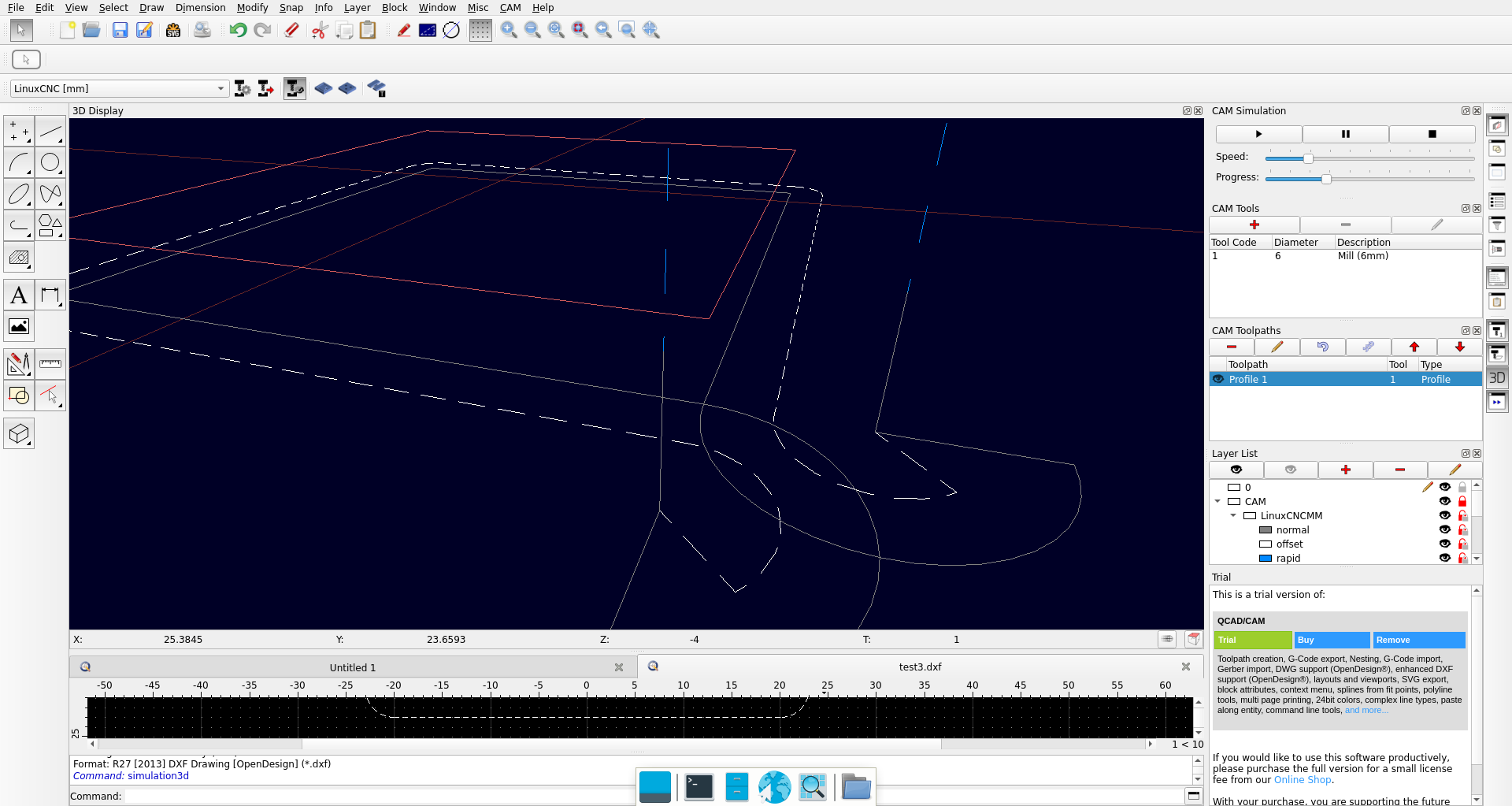
The postprocessor LinuxCNC [mm] is expected to use G41/42 cutter compensation.

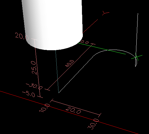
The Arcs of the red trajectories drawn at 10 units from the green shapes are correct entry moves for a calculated offset path.
With G41/42 active it is the green shape that is exported in G-code, when not it is the red path.
For G41/42 the driver internally calculate the required left or right center trajectory of your cutter.
There is no detailed information send back that you can visualize.
QCAD/CAM only visualize the expected central path ...

The motions to the Arc center in the 3D Display are already very odd :o
But they can be considered as correct compensation moves along a straight pre-entry move.
Why that is not tangent to the start of the circular entry move remains open.
The general idea is to smooth the motions and avoiding hard corners where possible.

It is indeed problematic with (additional) circular entry moves.
Something similar was already addressed in FS#2558 and related forum topic t10724.

With cutter compensation:
Attached to FS#2558 is a snippet of a document that explains to use a straight pre-entry move.
Because it is NOT POSSIBLE to compensate an Arc entry gradually with another Arc-like path.
Most drivers can not cope with the true trajectory of offsetting an Arc from zero to Rcutter along the Arc.
Supported G-code is typically limited to G0, G1, G2 or G3.

G41-Arc compensation.png
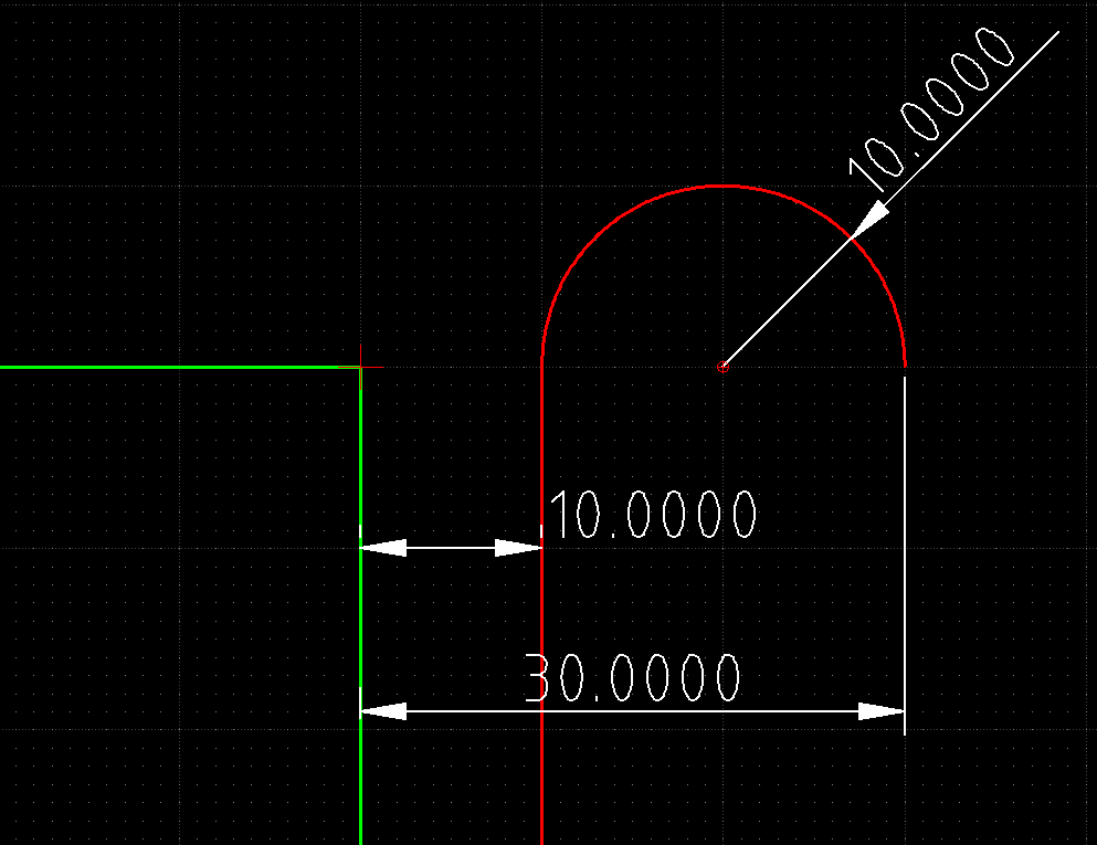
G41-Arc compensation.png (11.49 KiB) Viewed 18808 times

In the above the blue arc is a 3 point arc connecting the compensated cutter centers at 0-45-90°.
It doesn't connect tangentially to the horizontal blue path and doesn't match with other cutter center positions.
:arrow: The bulge of the blue central path would result in an over-cut for the entry path :!:
In magenta I added 1/4 of an ellipse, the only shape that will be tangent at start and end but it doesn't match with any other center position.
The true trajectory that connects the compensated cutter centers is a part of some spiral function.
Typically UNSUPPORTED.

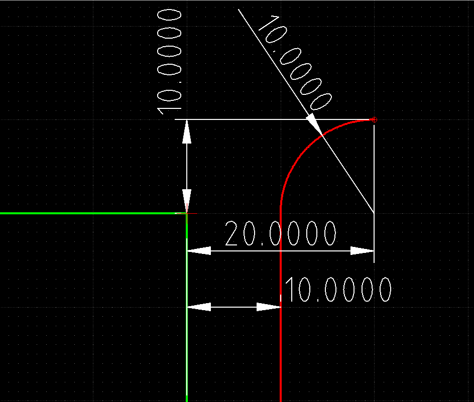
Common in G41/42 trajectory visualization is that the center path and the edge of the cut area start at the same point.
As if the cutter grows from R=zero to R=Rcutter along the entry trajectory.
I find the visualization of curved compensation paths in QCAM incorrect or at least misleading.
An offset to those central paths by Rcutter may even result in over-cutting.
A hunch ... I can not verify that with my CNC setup.

'As is' QCAD/CAM only supports plunging straight down and cylindrical cutters.
Plunging at the start of the entry move results in the orange dotted representation of the cutter.
The cutter edge is not matching with the cut area in white :!:
Plunging at the end of the entry move is no longer a circular motion that gradually approaches the area to cut :!:
Only plunging after a straight pre-entry move is correct.
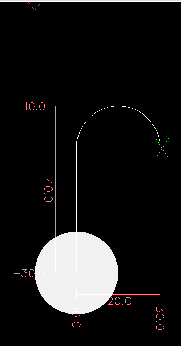

Calculated offset:
My CNC driver fails critical and displays a warning for an initial Arc-entry in combination with G41/42.
What limits my personal use of QCAD/CAM to a calculated offset path.

Then the center path and the edge of the cut area should NEVER start in the same point :!:
In the related topic there are several examples of false trajectories (also called 'donkey ears') and the proper representations.

FS#2558 was rejected and closed based on 'No DXF file provided'. (Why)
But 3 months later, for a similar report t10951 a new Bug Report FS#2584 was opened by Andrew himself and later resolved.


Milling 'On path':
Basically nothing more than adding circular motions at start and end.
But it is debatable if that is still 'On path' and it is unclear from which side that should approach the drawn path.

Curved entry paths at corners is also debatable.
They are usually added where you approach a face to mill.

Regards,
CVH

tuxcnc
Registered Member
Posts: 2
Joined: Wed Sep 03, 2025 5:31 pm

Re: Bad entrance

Post by tuxcnc » Thu Sep 04, 2025 12:24 pm

CVH wrote:
Thu Sep 04, 2025 6:10 am
Hi and welcome to the QCAD forum.

Please specify your QCAD/CAM (trial) version.
Please attach a CAM drawing file (Read lower 'Why') and the exported G-Code file.
Hi.

The version of file is qcadcam-3.32.3-trial-linux-qt5.14-x86_64.run, drawing is a simply rectangle.
Gcode generated by QCAD:

Code: Select all

N10 G10 L1 P1 R3
N20 G0 Z50
N30 G0 X27 Y20
N40 T1 M6
N50 S1000 M03
N60 G0 Z2
N70 G1 Z-4 F300
N80 F1000
N90 G41 X34
N100 G3 X20 I-7 J0
N110 G1 Y-20
N120 X-20
N130 Y20
N140 X20
N150 G3 Y34 I0 J7
N160 G40 G1 Y27
N170 Z2
N180 G0 Z50
N190 M30

=============================


Let's go back to this drawing:

Image

This is written myself code for cut this:

Code: Select all

G10 L1 P1 R10
M6 T1
S1000 F1000
G0 Z20
G0 X30 Y0
G1 Z-5
G41
G3 X0 I-15 J0
G1 Y-30
G40 X10
G0 Z20
M30
This is the LinuxCNC previews:
Image
Image

Some tricks, but no wonders.
Only mathematics...

CVH
Premier Member
Posts: 4954
Joined: Wed Sep 27, 2017 4:17 pm

Re: Bad entrance

Post by CVH » Thu Sep 04, 2025 1:55 pm

Hi,
tuxcnc wrote:
Thu Sep 04, 2025 12:24 pm
This is written myself code for cut this
Missing: The 3 other sides, the circular paths around the corners and the exit move.
tuxcnc wrote:
Thu Sep 04, 2025 12:24 pm
Let's go back to this drawing:
...
Some tricks, but no wonders.
It was in my reply:
The offset path you drew is the calculated offset path with for example the postprocessor LinuxCNC (Offset) [mm]
Then QCAD/CAM constructs the offset for you and exports that as G-Code using G40 globally.
The controller follows the path defined in G-code to the letter.

Using LinuxCNC [mm] you rely on the controller to offset the path in the correct manner.
The controller does not follow the path as defined in G-code, it follows an offset path to what is stored in G-code.
QCAD/CAM only visualizes the expected central path beside the result ... There is no feedback on what the controller will do.

In your G-code we see a linear move to X34 (still Y20) after the G41.
What is good practice but I would orient my straight pre-entry move differently for continuous motion.

My controller would reject G41 followed by a circular entry path as impossible.
Using G41/42 with circular lead In/Out always failed before.

Let's have a look at the generated G-code:
N10 -> Header block defined in LinuxCNC.js (The base for LinuxCNCMM.js and for LinuxCNCOffsetMM.js)
N20 -> Move fast upward to safety.
N30 -> Traverse to X27 Y20
N40-50 -> Tool 1, activate spindel
N60 -> Plunge fast to Z2 (+2 thus above the material)
N70 -> Plunge slow to Z-4 (G1 is modal until altered)
N80 -> New Feedrate
N90 -> Activate cutter compensation for a G1 motion from X27 Y20 to X34 Y20
... Target Y was not specified because it doesn't change.
... The endpoint of this compensation path is not specified in G-code, it is known by the controller.
N100 -> A 180° circular motion to X20 Y20
... The edge arc presented in the 3D display looks indeed as a semi-circle.
... The central path arc doesn't has the complete 180°sweep.
... In reality that started at the former end position, the end after the linear compensated pre-entry.
N120-N140 G1 motions: 20 left - 20 down - 20 right - 20 up
... The square shape you defined as source shape (Not really a rectangle but a special form of a rectangle :wink: )
... The central path is larger as the controller is still compensating.
... At the corners you see it compensating as an arc but there is no G2/3 motion included at the corners.

The Lead Out is pretty much the same as the Lead In.

The advantage of G41/42 is that you specify what must be cut and the offset is quasi automatically.
G-code can be somewhat more compact because instructions for corner compensation are not required.
That may play a role for very complex projects.

Yes, QCAD shows two contours.
One is the edge of cutter, the shape as per G-code.
The other is the central path followed by the cutter as expected from a cutter compensation by the controller.
Nothing of that second path is in the G-Code except the traverse an plunge at the start and the retract at the end.
Because there the compensation is off, the virtual tool radius is considered as zero and paths coincides.

For milling a square with a 20 mm side, starting and ending at a corner with a half-circle as Lead In/Out using G41/G42 cutter compensation ...
... I must conclude that there is nothing wrong.

Perhaps you could give the CAM layers a different color related to the meaning.
They already use different Linetypes.

Regards,
CVH

Post Reply

Return to “QCAD/CAM”